CYLINDER BLOCK REASSEMBLY

Tech Tips
w/ Canister Pump Module:
Perform "Inspection After Repairs" after replacing the piston sub-assembly or piston ring Click here.
-
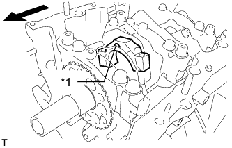
INSTALL NO. 1 OIL NOZZLE SUB-ASSEMBLY
-
Using a 5 mm hexagon wrench, install the No. 1 oil nozzle sub-assemblies with the 3 bolts.
- Torque:
- 9.0 N*m { 92 kgf*cm, 80 in.*lbf }
-
-
INSTALL CONNECTING ROD SMALL END BUSH
-
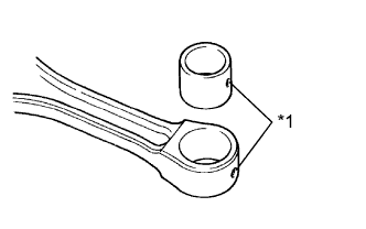
Text in Illustration *1 Oil Hole Align the oil holes of a new bush and the connecting rod.
-
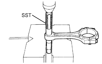
Using SST and a press, press in the bush.
- SST
- 09222-30010
-
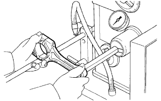
Using a pin hole grinder, hone the bush to obtain the specified clearance between the bush and piston pin.
Standard oil clearance -0.002 to 0.004 mm (-0.0000787 to 0.000156 in.) -
Check that the piston pin fits at normal room temperature.
-
Coat the piston pin with engine oil, and push it into the connecting rod with your thumb.
-
-
INSTALL PISTON SUB-ASSEMBLY WITH PIN
Tech Tips
w/ Canister Pump Module:
Perform "Inspection After Repairs" after replacing the piston Click here.
-
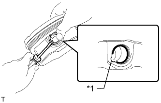
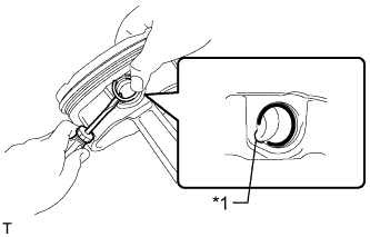
Text in Illustration *1 Cutout Portion Using a screwdriver, install a new piston pin hole snap ring at one end of the piston pin hole.
Tech Tips
Confirm that the end gap of the snap ring is not aligned with the pin hole cutout portion of the piston.
-
Gradually heat the piston to approximately 80°C (176°F).
-
Coat the piston pin with engine oil.
-
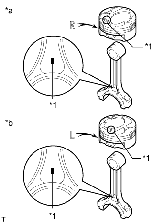
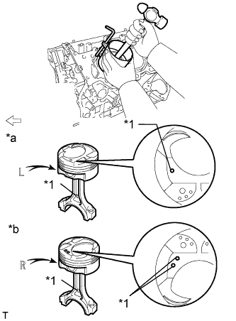
Text in Illustration *1 Front Mark *a Piston RH *b Piston LH Align the front marks of the piston and connecting rod, and push in the piston pin with your thumb.
Tech Tips
The piston and pin are a matched set.
-
Check the fitting condition between the piston and piston pin by trying to move the piston back and forth on the piston pin.
-
Text in Illustration *1 Cutout Portion Using a screwdriver, install a new piston pin hole snap ring at the other end of the piston pin hole.
Tech Tips
Confirm that the end gap of the snap ring is not aligned with the pin hole cutout portion of the piston.
-
-
INSTALL PISTON RING SET
Tech Tips
w/ Canister Pump Module:
Perform "Inspection After Repairs" after replacing the piston ring Click here.
-
Install the oil ring expander and 2 side rails by hand.
-
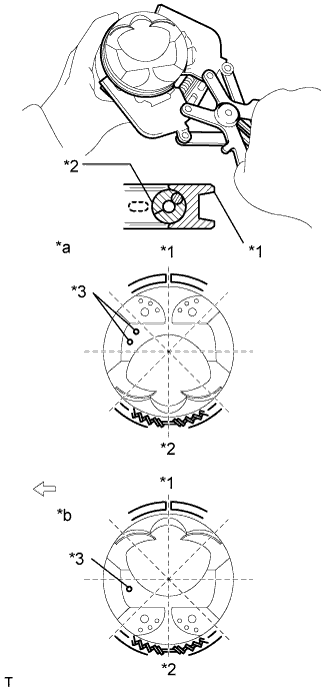
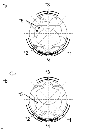
Text in Illustration *1 Oil Ring *2 Oil Ring Expander *3 Front Mark *a Piston RH *b Piston LH 
Engine Front Using a piston ring expander, install the oil ring rail as shown in the illustration.
-
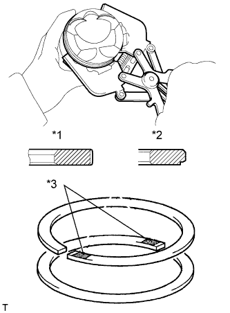
Text in Illustration *1 No. 1 Ring *2 No. 2 Ring *3 Code Mark Using a piston ring expander, install the 2 compression rings so that the painted marks are positioned as shown in the illustration.
Tech Tips
-
Install the compression ring No. 1 with the code mark (1N) facing upward.
-
Install the compression ring No. 2 with the code mark (2N) facing upward.
-
-
Text in Illustration *1 No. 1 Ring *2 No. 2 Ring *3 Front Mark *a Piston RH *b Piston LH Engine Front Position the piston rings so that the ring ends are as shown in the illustration.
Note
Do not align the ring ends.
-
-
INSTALL CRANKSHAFT BEARING
-
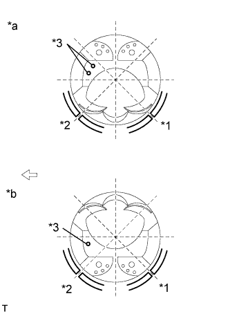
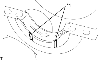
Text in Illustration *1 No. 1 and No. 4 Journal Bearing *2 No. 2 and No. 3 Journal Bearing Clean the main journal and both surfaces of the bearings.
Note
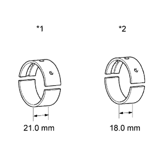
Main bearings come in widths between 18.0 mm (0.709 in.) and 21.0 mm (0.827 in.). Install the 21.0 mm (0.827 in.) bearings in the No. 1 and No. 4 cylinder block journal positions with the main bearing cap. Install the 18.0 mm (0.709 in.) bearings in the No. 2 and No. 3 positions.
-
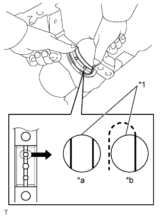
Text in Illustration *1 Upper Bearing *a CORRECT *b INCORRECT Install the upper crankshaft bearing.
-
Install the upper crankshaft bearings to the cylinder block as shown in the illustration.
Note
-
Do not apply engine oil to the bearings and the contact surfaces.
-
Both sides of the oil groove in the cylinder block should be visible through the oil feed holes in the bearing. The amount visible on each side of the holes should be equal.
-
Do not allow coolant to come into contact with the bearing inner surface.
-
If any coolant comes into contact with the bearing inner surface, replace the bearing with a new one.
-
-
-
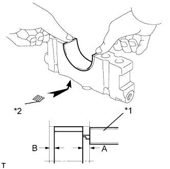
Text in Illustration *1 Vernier Caliper *2 Mark 1, 2, 3, 4 or 5 Install the lower crankshaft bearing.
-
Install the lower crankshaft bearings to the crankshaft bearing caps.
-
Using a vernier caliper, measure the distance between the crankshaft bearing cap edge and the lower crankshaft bearing edge.
Standard Dimension (A - B or B - A) 0.7 mm (0.0276 in.) or less Note
-
Do not apply engine oil to the crankshaft bearings and the contact surfaces.
-
Do not allow coolant to come into contact with the bearing inner surface.
-
If any coolant comes into contact with the bearing inner surface, replace the bearing with a new one.
-
-
-
-
INSTALL CRANKSHAFT THRUST WASHER SET
-
Apply engine oil to the crankshaft thrust washer.
-
Text in Illustration *1 Oil Grooves Install the 2 upper crankshaft thrust washers under the No. 2 journal position of the cylinder block sub-assembly with the oil grooves facing outward.
-
-
INSTALL CRANKSHAFT
-
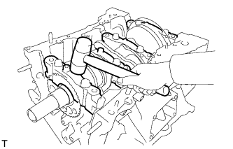
Apply engine oil to the upper bearing, and then place the crankshaft on the cylinder block.
-
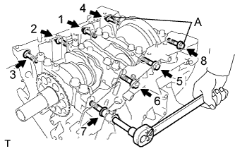
Text in Illustration *1 Projection *2 Number Mark Confirm the projections and numbers on the main bearing caps and install the crankshaft bearing caps on the cylinder block.
Tech Tips
A number is marked on each main bearing cap to indicate the installation position.
-
Apply a light coat of engine oil to the threads and under the heads of the crankshaft bearing cap bolts.
-
Temporarily install the 8 crankshaft bearing cap bolts to the inside positions.
-
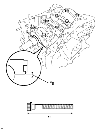
Text in Illustration *1 Bolt Length *a Less than 6 mm (0.236 in.) Insert the crankshaft bearing cap with your hand until the clearance between the crankshaft bearing cap and the cylinder block is less than 6 mm (0.236 in.) by marking the 2 internal crankshaft bearing cap bolts as a guide.
Bolt Length 100 to 102 mm (3.937 to 4.0157 in.) -
Using a plastic-faced hammer, lightly tap the crankshaft bearing cap to ensure a proper fit.
-
Apply a light coat of engine oil to the threads and under the heads of the 8 crankshaft bearing cap bolts.
-
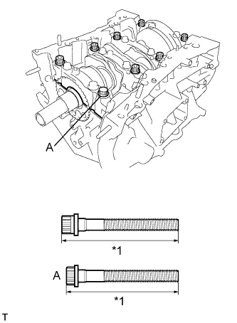
Text in Illustration *1 Bolt Length Install the 8 crankshaft bearing cap bolts to the outside positions.
Bolt Length Item Specified Condition Bolt A 100 to 102 mm (3.94 to 4.02 in.) Except bolt A 105.5 to 107.5 mm (4.15 to 4.23 in.) -
Install the crankshaft bearing cap bolts.
Tech Tips
The crankshaft bearing cap bolts are tightened in 2 progressive steps.
-
Step 1
-
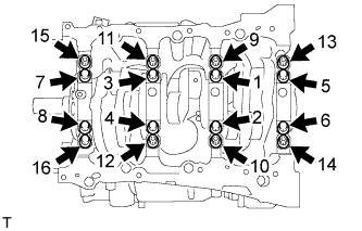
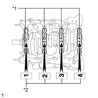
Install and uniformly tighten the 16 crankshaft bearing cap bolts in several steps and in the sequence shown in the illustration.
- Torque:
- 61 N*m { 622 kgf*cm, 45 ft.*lbf }
If any of the crankshaft bearing cap bolts does not meet the torque specified, replace it.
-
-
Step 2
-
Mark the front of the bearing cap bolts with paint.
-
Tighten the cap bolts another 90°.
-
Check that the painted marks are now at a 90° angle to the front of the engine.
-
-
Install 8 new seal washers and uniformly tighten the 8 crankshaft bearing cap bolts in several steps and in the sequence shown in the illustration.
- Torque:
- 26 N*m { 262 kgf*cm, 19 ft.*lbf }
Bolt Length Item Specified Condition Bolt A 45 mm (1.77 in.) Except bolt A 30 mm (1.18 in.) -
Check that the crankshaft turns smoothly.
-
Check the crankshaft thrust clearance Click here.
-
-
INSTALL CONNECTING ROD BEARING
-
Install the connecting rod bearings to the connecting rod and connecting rod cap.
-
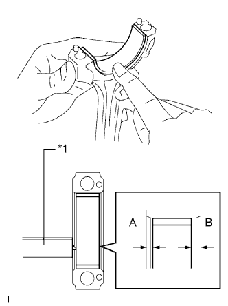
Text in Illustration *1 Vernier Caliper Using a vernier caliper, measure the distance between each connecting rod bearing edge and the connecting rod edges, and the connecting rod cap edges respectively.
Standard Dimension (A - B or B - A) 0.7 mm (0.0276 in.) or less Note
Do not apply engine oil to the bearings and the contact surfaces.
-
-
INSTALL PISTON SUB-ASSEMBLY WITH CONNECTING ROD
-
Apply engine oil to the cylinder walls, the pistons, and the surfaces of the connecting rod bearings.
-
Text in Illustration *1 No. 1 Ring *2 No. 2 Ring *3 Oil Ring *4 Oil Ring Expander *5 Front Mark *a Piston RH *b Piston LH Engine Front Position the piston rings so that the ring ends are as shown in the illustration.
Note
Do not align the ring ends.
-
Text in Illustration *1 Front Mark *a Piston LH *b Piston RH Engine Front Using a piston ring compressor, push the correctly numbered piston and connecting rod assembly into the cylinder with the front mark of the piston facing forward.
Note
Match the numbered connecting rod cap with the connecting rod.
-
Text in Illustration *1 Front Mark 
Engine Front Check that the front mark of the connecting rod cap is facing forward.
-
Apply a light coat of engine oil to the threads and under the heads of the connecting rod cap bolts.
-
Install the connecting rod cap bolts.
Tech Tips
The cap bolts are tightened in 2 progressive steps.
-
Step 1
-
Install and alternately tighten the bolts of each connecting rod cap in several steps.
- Torque:
- 40 N*m { 408 kgf*cm, 30 ft.*lbf }
-
Mark the front side of each connecting rod cap bolt with paint.
-
-
Step 2
-
Tighten the cap bolts 90°.
-
-
Check that the paint marks are now at a 90° angle to the front.
-
Check that the crankshaft turns smoothly.
-
-
INSPECT CONNECTING ROD THRUST CLEARANCE
-
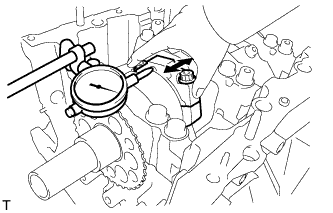
Using a dial indicator, measure the thrust clearance while moving the connecting rod back and forth.
Standard thrust clearance 0.15 to 0.40 mm (0.00591 to 0.0157 in.) Maximum thrust clearance 0.50 mm (0.0197 in.) If the thrust clearance is more than the maximum, replace the connecting rod assemblies as necessary. If necessary, replace the crankshaft.
-