AIR FUEL RATIO SENSOR REMOVAL

-
REMOVE POWER STEERING ECU ASSEMBLY
-
REMOVE ENGINE ROOM SIDE COVER
-
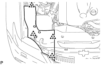
Remove the 4 clips and engine room side cover.
-
-
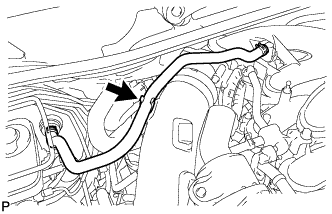
REMOVE COOL AIR INTAKE DUCT SEAL
-
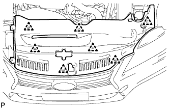
Remove the 7 clips and cool air intake duct seal.
-
-
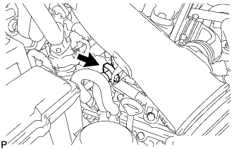
REMOVE V-BANK COVER SUB-ASSEMBLY
-
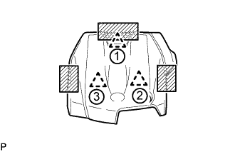
Place one hand on the rear of the cover as shown in the illustration and detach the clip near the rear. Then, place both hands on the sides of the cover and lift the cover to detach the 2 clips near the front in the order shown in the illustration to remove the cover.
Text in Illustration 
Areas to place hands when lifting cover Note
If the cover is lifted rearward or forward and to the right or left at the same time, the cover maybe damaged.
-
-
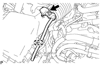
DISCONNECT NO. 2 VENTILATION HOSE
-
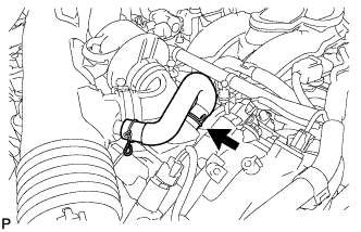
Disconnect the ventilation hose from the cylinder head.
-
-
REMOVE AIR CLEANER CAP WITH AIR CLEANER HOSE
-
Disconnect the mass air flow meter connector.
-
Disconnect the clamp from the air cleaner.
-
Disconnect the VSV hose.
-
for RHD:
Disconnect the union to check valve hose.
-
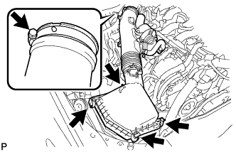
Disconnect the 4 clamps.
-
Remove the hose clamp and air cleaner cap with air cleaner hose.
-
-
REMOVE BATTERY TRAY (for LHD)
-
Detach the fuel pipe clamp.
-
Remove the 2 bolts and battery tray.
-
-
REMOVE BATTERY TRAY (for RHD)
-
Remove the 2 bolts and battery tray.
-
-
SEPARATE NO. 4 ENGINE WIRE (for LHD)
-
Remove the engine room No. 1 relay block cover.
-
Detach the 2 wire harness clamps.
-
Remove the nut and separate the No. 4 engine wire from the engine room No. 1 junction block.
-
-
SEPARATE NO. 4 ENGINE WIRE (for RHD)
-
Remove the engine room No. 1 relay block cover.
-
Detach the wire harness clamp.
-
Remove the nut and separate the No. 4 engine wire from the engine room No. 1 junction block.
-
-
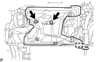
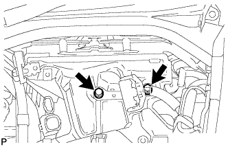
DISCONNECT RELAY BLOCK ASSEMBLY
-
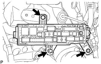
Remove the 2 bolts and nut and disconnect the relay block assembly.
-
-
REMOVE AIR FUEL RATIO SENSOR
-
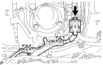
for Bank 1 Sensor 1:
Disconnect the air fuel ratio sensor connector.
-
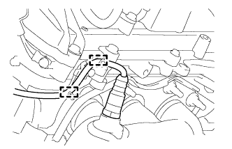
Detach the 2 wire harness clamps.
-
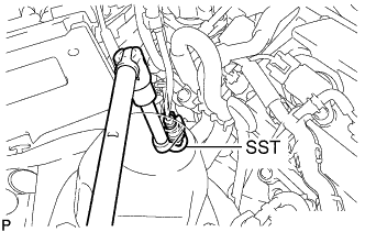
Using SST, remove the air fuel ratio sensor.
- SST
- 09224-00010
-
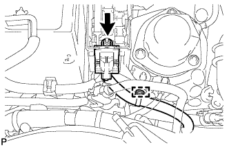
for Bank 2 Sensor 1:
Disconnect the air fuel ratio sensor connector.
-
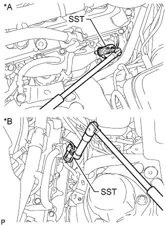
Using SST, remove the air fuel ratio sensor.
- SST
- 09224-00010
-