SFI SYSTEM ACIS Control Circuit
DESCRIPTION
When the Intake Air Control Valve (IACV) opens and closes, the Acoustic Control Induction System (ACIS) control circuit causes the engine load intake efficiency to increase. When the engine is running at 2200 to 4300 rpm and the throttle valve opening angle is 30° or more, current flows through the ACIS control circuit and the intake air control valve closes. For all other situations, current does not flow through the ECM and the intake air control valve is open.
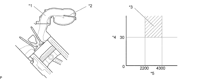
| *1 | Intake Manifold | *2 | Intake Air Control Valve (IACV) |
| *3 | IACV Close | *4 | Throttle Valve Opening Angle (°) |
| *5 | Engine Speed (rpm) | - | - |
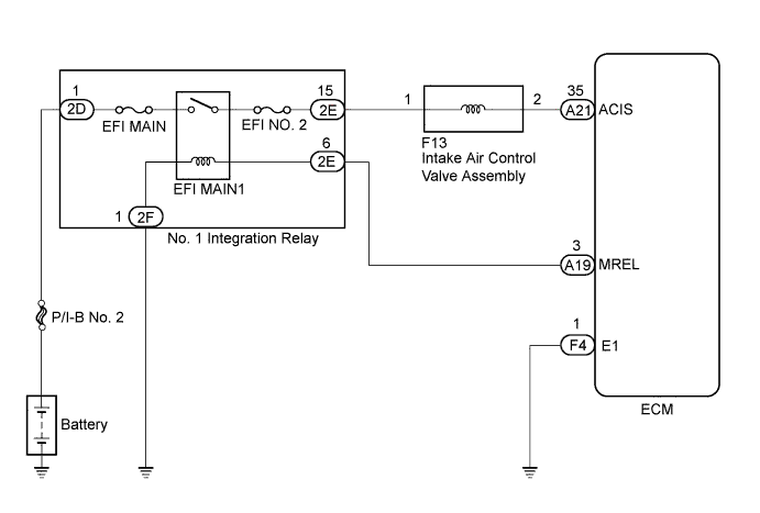
WIRING DIAGRAM
INSPECTION PROCEDURE
Note
Inspect the fuses for circuits related to this system before performing the following inspection procedure.
PROCEDURE
-
PERFORM ACTIVE TEST USING GTS (OPERATE INTAKE AIR CONTROL VALVE)
-
Connect the GTS to the DLC3.
-
Start the engine and turn the GTS on.
-
Enter the following menus: Powertrain / Engine and ECT / Active Test / Activate the VSV for Intake Control.
-
Check if operating noise can be heard when operating the intake control valve using the GTS.
OK Operating noise can be heard.
NG 
CHECK INTAKE AIR CONTROL VALVE ASSEMBLY (OPERATION) Click here
OK 
PROCEED TO NEXT SUSPECTED AREA SHOWN IN PROBLEM SYMPTOMS TABLE Click here
-
-
CHECK INTAKE AIR CONTROL VALVE ASSEMBLY (OPERATION)
-
Inspect the intake air control valve assembly Click here.
NG 
REPLACE INTAKE AIR SURGE TANK ASSEMBLY Click here
OK 
-
-
CHECK HARNESS AND CONNECTOR (INTAKE AIR CONTROL VALVE ASSEMBLY VOLTAGE)
-
Disconnect the intake air control valve assembly connector.
-
Turn the engine switch on (IG).
-
Measure the voltage according to the value(s) in the table below.
Standard Voltage Tester Connection Switch Condition Specified Condition F13-1 - Body ground Engine switch on (IG) 11 to 14 V -
Reconnect the intake air control valve assembly.
NG
REPAIR OR REPLACE HARNESS OR CONNECTOR (EFI MAIN RELAY - INTAKE AIR CONTROL VALVE ASSEMBLY)
OK
-
-
CHECK HARNESS AND CONNECTOR (INTAKE AIR CONTROL VALVE ASSEMBLY - ECM)
-
Disconnect the intake air control valve assembly connector.
-
Disconnect the ECM connector.
-
Measure the resistance according to the value(s) in the table below.
Standard Resistance Tester Connection Condition Specified Condition F13-2 - A21-35 (ACIS) Always Below 1 Ω F13-2 or A21-35 (ACIS) - Body ground Always 10 kΩ or higher -
Reconnect the intake air control valve assembly connector.
-
Reconnect the ECM connector.
NG
REPAIR OR REPLACE HARNESS OR CONNECTOR
OK
REPLACE ECM Click here
-