SFI SYSTEM, Diagnostic DTC:P0660

| DTC Code | DTC Name |
|---|---|
| P0660 | Intake Manifold Tuning Valve Control Circuit / Open (Bank 1) |
DESCRIPTION
When the Intake Air Control Valve (IACV) opens and closes, the Acoustic Control Induction System (ACIS) control circuit causes the engine load intake efficiency to increase. When the engine is running at 2200 to 4300 rpm and the throttle valve opening angle is 30° or more, current flows through the ACIS control circuit and the intake air control valve closes. For all other situations, current does not flow through the ECM and the intake air control valve is open.
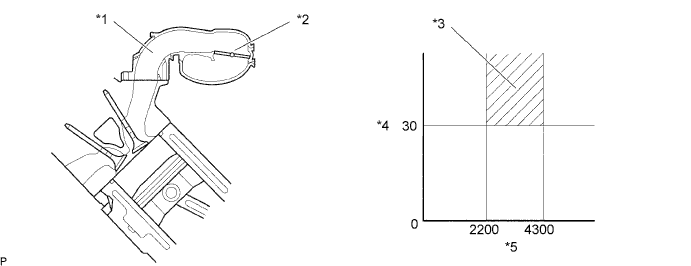
| *1 | Intake Manifold | *2 | Intake Air Control Valve (IACV) |
| *3 | IACV Close | *4 | Throttle Valve Opening Angle (°) |
| *5 | Engine Speed (rpm) | - | - |
| DTC No. | DTC Detection Condition | Trouble Area |
|---|---|---|
| P0660 | The following conditions are met simultaneously for 0.5 seconds or more (2 trip detection logic):
|
|
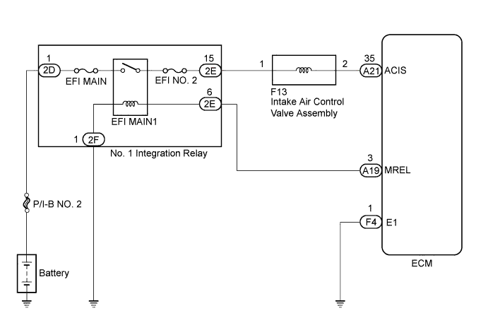
WIRING DIAGRAM
INSPECTION PROCEDURE
Note
Inspect the fuses for circuits related to this system before performing the following inspection procedure.
Tech Tips
Read freeze frame data using the GTS. The ECM records vehicle and driving condition information as freeze frame data the moment a DTC is stored. When troubleshooting, freeze frame data can help determine if the vehicle was moving or stationary, if the engine was warmed up or not, if the air fuel ratio was lean or rich, and other data from the time the malfunction occurred.
PROCEDURE
-
PERFORM ACTIVE TEST USING GTS
-
Connect the GTS to the DLC3.
-
Turn the engine switch on (IG) and turn the tester on.
-
Enter the following menus: Powertrain / Engine and ECT / Active Test / Activate the VSV for Intake Control.
-
Check if operating noise can be heard when operating the intake control valve using the GTS.
OK Operating noise can be heard.
NG 
CHECK INTAKE AIR SURGE TANK ASSEMBLY (INTAKE AIR CONTROL VALVE ASSEMBLY OPERATION) Click here
OK 
CHECK FOR INTERMITTENT PROBLEMS Click here
-
-
CHECK INTAKE AIR SURGE TANK ASSEMBLY (INTAKE AIR CONTROL VALVE ASSEMBLY OPERATION)
-
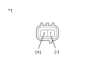
Text in Illustration *1 Component without harness connected
(Intake Air Control Valve Assembly)
Disconnect the intake air control valve assembly connector.
-
Apply battery voltage between the terminals of the intake air control valve assembly connector.
-
Check the intake air control valve assembly operation.
OK Operating noise can be heard. -
Reconnect the intake air control valve assembly connector.
NG 
REPLACE INTAKE AIR SURGE TANK ASSEMBLY Click here
OK 
-
-
CHECK HARNESS AND CONNECTOR (INTAKE AIR CONTROL VALVE ASSEMBLY VOLTAGE)
-
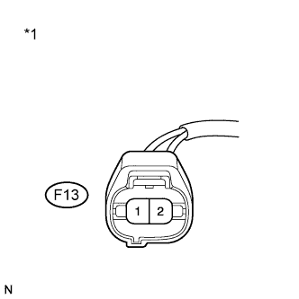
Text in Illustration *1 Front view of wire harness connector
(to Intake Air Control Valve Assembly)
Disconnect the intake air control valve assembly connector.
-
Turn the engine switch on (IG).
-
Measure the voltage according to the value(s) in the table below.
Standard Voltage Tester Connection Switch Condition Specified Condition F13-1 - Body ground Engine switch on (IG) 11 to 14 V -
Reconnect the intake air control valve assembly connector.
NG
REPAIR OR REPLACE HARNESS OR CONNECTOR (EFI MAIN RELAY - INTAKE AIR CONTROL VALVE ASSEMBLY)
OK
-
-
CHECK HARNESS AND CONNECTOR (INTAKE AIR CONTROL VALVE ASSEMBLY - ECM)
-
Disconnect the intake air control valve assembly connector.
-
Disconnect the ECM connector.
-
Measure the resistance according to the value(s) in the table below.
Standard Resistance Tester Connection Condition Specified Condition F13-2 - A21-35 (ACIS) Always Below 1 Ω F13-2 or A21-35 (ACIS) - Body ground Always 10 kΩ or higher -
Reconnect the intake air control valve assembly connector.
-
Reconnect the ECM connector.
NG
REPAIR OR REPLACE HARNESS OR CONNECTOR
OK
REPLACE ECM Click here
-