SFI SYSTEM, Diagnostic DTC:P0500

| DTC Code | DTC Name |
|---|---|
| P0500 | Vehicle Speed Sensor "A" |
DESCRIPTION
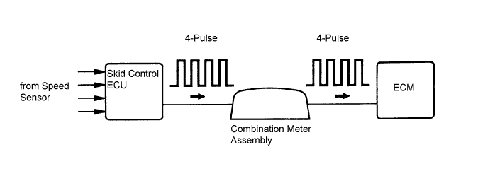
The wheel speed sensors monitor the wheel rotation speed and send signals to the skid control ECU. The skid control ECU converts the wheel speed signal into a 4-pulse signal and transmits it to the ECM via the combination meter assembly. The ECM determines the vehicle speed based on the frequency of the pulse signal.
Tech Tips
-
A voltage of 12 V or 5 V is output from each ECU and then input to the combination meter assembly. The signal is changed to a pulse signal at the transistor in the combination meter assembly. Each ECU controls the respective system based on the pulse signal.
-
If a short occurs in any of the ECUs or in the wire harness connected to an ECU, all systems in the wiring diagram below will not operate normally.
| DTC No. | DTC Detection Condition | Trouble Area |
|---|---|---|
| P0500 | While vehicle being driven, no vehicle speed sensor signal transmitted to ECM (2 trip detection logic) |
|
MONITOR DESCRIPTION
If there is no speed signal from the combination meter assembly even though the ECM determines that the vehicle is being driven, the ECM interprets this as a malfunction in the speed signal circuit. The ECM then illuminates the MIL and sets the DTC.
MONITOR STRATEGY
| Required sensors/components (Main) | Vehicle speed sensor, combination meter assembly and skid control ECU |
| Required sensors/components (Related) | Park/Neutral position switch assembly, engine coolant temperature sensor, crankshaft position sensor, throttle position sensor and mass air flow meter |
| Frequency of operation | Continuous |
TYPICAL ENABLING CONDITIONS
| Vehicle speed at output speed sensor | 9 km/h (5.59 mph) or more |
TYPICAL MALFUNCTION THRESHOLDS
| Vehicle speed sensor signal | No signal |
CONFIRMATION DRIVING PATTERN
-
Connect the GTS to the DLC3.
-
Turn the engine switch on (IG) and turn the GTS on.
-
Clear the DTCs (even if no DTCs are stored, perform the clear DTC procedure) Click here.
-
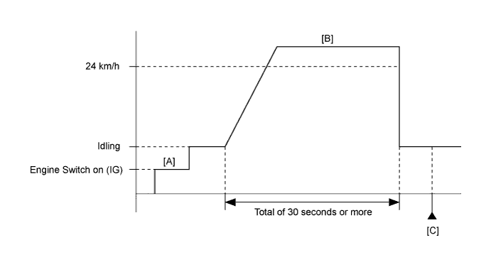
Turn the engine switch off and wait for at least 30 seconds.
-
Turn the engine switch on (IG) and turn the GTS on [A].
-
Start the engine.
-
Drive the vehicle at 24 km/h (15 mph) or more for a total of 30 seconds or more [B].
CAUTION:
When performing the confirmation driving pattern, obey all speed limits and traffic laws.
-
Stop the vehicle.
-
Enter the following menus: Powertrain / Engine and ECT / Trouble Codes [C].
-
Read Pending DTCs.
Tech Tips
-
If a pending DTC is output, the system is malfunctioning.
-
If a pending DTC is not output, perform the following procedure.
-
-
Enter the following menus: Powertrain / Engine and ECT / Utility / All Readiness.
-
Input the DTC: P0500.
-
Check the DTC judgment result.
GTS Display Description NORMAL
-
DTC judgment completed
-
System normal
ABNORMAL
-
DTC judgment completed
-
System abnormal
INCOMPLETE
-
DTC judgment not completed
-
Perform driving pattern after confirming DTC enabling conditions
N/A
-
Unable to perform DTC judgment
-
Number of DTCs which do not fulfill DTC preconditions has reached ECU's memory limit
Tech Tips
-
If the judgment result shows NORMAL, the system is normal.
-
If the judgment result shows ABNORMAL, the system has a malfunction.
-
-
If the test result is INCOMPLETE or N/A and no pending DTC is output, perform a universal trip and check for permanent DTCs Click here.
Tech Tips
-
If a permanent DTC is output, the system is malfunctioning.
-
If no permanent DTC is output, the system is normal.
-
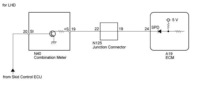
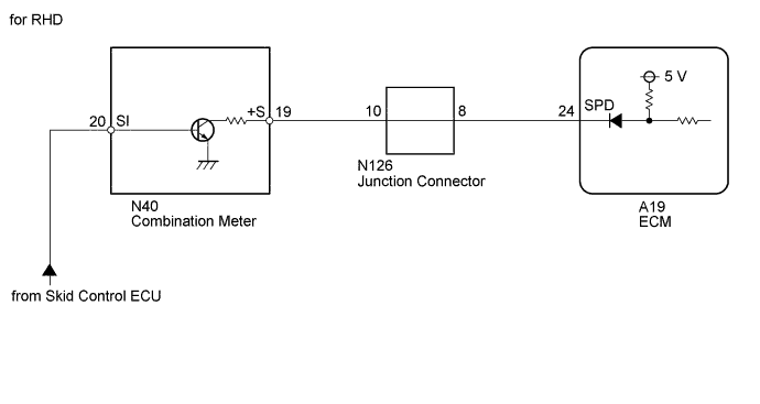
WIRING DIAGRAM
INSPECTION PROCEDURE
Tech Tips
Read freeze frame data using the GTS. The ECM records vehicle and driving condition information as freeze frame data the moment a DTC is stored. When troubleshooting, freeze frame data can help determine if the vehicle was moving or stationary, if the engine was warmed up or not, if the air fuel ratio was lean or rich, and other data from the time the malfunction occurred.
PROCEDURE
-
READ VALUE USING GTS (VEHICLE SPEED)
-
Connect the GTS to the DLC3.
-
Turn the engine switch on (IG).
-
Turn the GTS on.
-
Enter the following menus: Powertrain / Engine and ECT / Data List / Vehicle Speed.
-
Drive the vehicle.
-
Read the value displayed on the GTS.
OK Vehicle speeds displayed on GTS and speedometer display are equal.
NG 
CHECK COMBINATION METER SYSTEM Click here
OK 
CHECK FOR INTERMITTENT PROBLEMS Click here
-
-
CHECK COMBINATION METER SYSTEM
-
Inspect the circuits that send vehicle speed signals to this system in the meter system Click here.
-
During inspection for the meter section, if there is an instruction that indicates to go back to inspections for each system, proceed to the next step.
NEXT 
-
-
CHECK HARNESS AND CONNECTOR (COMBINATION METER ASSEMBLY - ECM)
-
Disconnect the combination meter assembly connector.
-
Disconnect the ECM connector.
-
Measure the resistance according to the value(s) in the table below.
Standard Resistance Tester Connection Condition Specified Condition N40-19 (+S) - A19-24 (SPD) Always Below 1 Ω
NG
CHECK HARNESS AND CONNECTOR (JUNCTION CONNECTOR - ECM) Click here
OK
REPLACE ECM Click here
-
-
CHECK HARNESS AND CONNECTOR (JUNCTION CONNECTOR - ECM)
-
Disconnect the junction connector.
-
Disconnect the ECM connector.
-
Measure the resistance according to the value(s) in the table below.
Standard Resistance for LHD Tester Connection Condition Specified Condition N125-19 - A19-24 (SPD) Always Below 1 Ω for RHD Tester Connection Condition Specified Condition N126-8 - A19-24 (SPD) Always Below 1 Ω
NG 
REPAIR OR REPLACE HARNESS OR CONNECTOR (JUNCTION CONNECTOR - ECM)
OK
REPAIR OR REPLACE HARNESS OR CONNECTOR (JUNCTION CONNECTOR IS DEFECTIVE)
-