SFI SYSTEM, Diagnostic DTC:P2004, P2006

| DTC Code | DTC Name |
|---|---|
| P2004 | Intake Manifold Runner Control Stuck Open (Bank 1) |
| P2006 | Intake Manifold Runner Control Stuck Closed (Bank 1) |
DESCRIPTION
The Swirl Control Valves (SCV) are built into the intake manifold. The swirl control valves use a position sensor and a DC motor. A swirl control valve is located at one side of each pair of independent intake ports. Depending on signals from the ECM, the DC motor opens and closes the swirl control valves. The position sensor detects the opening angle of the swirl control valves. When the swirl control valves close, the velocity of the intake air flow that passes through the port on the other side of the independent intake port will become faster, enhancing lateral turbulent flow in the combustion chamber. As a result, when engine coolant temperature is low, atomization of fuel will be enhanced, stabilizing combustion in the cylinder. Also fuel consumption is decreased due to increased combustion efficiency when the engine is running at a low speed with a light load.
| DTC No. | DTC Detection Condition | Trouble Area |
|---|---|---|
| P2004 | The swirl control valve opening angle is 20° or more after requesting the swirl control valve full close (2 trip detection logic) |
|
| P2006 | The swirl control valve opening angle is less than 35° after requesting the swirl control valve full open (2 trip detection logic) |
Tech Tips
After confirming DTC P2004 or P2006, use the GTS to confirm the IAC Sensor Voltage (swirl control valve position sensor output voltage) while performing Control the SCV Duty Ratio of the Active Test.
| Control the SCV Duty Ratio | IAC Sensor Voltage |
|---|---|
| 100% | 3.2 to 4.8 V |
| -100% | 0.2 to 1.0 V |
MONITOR DESCRIPTION
When the ECM has requested a swirl control valve close operation but the swirl control valve's actual opening angle is 20° or more for 10 seconds, DTC P2004 is output. When the ECM has requested a swirl control valve open operation but the swirl control valve's actual opening angle is less than 35° for 10 seconds, DTC P2006 is output.
MONITOR STRATEGY
| Required sensors/components (Main) | Swirl control valve |
| Required sensors/components (Related) | Intake air temperature sensor, Engine coolant temperature sensor |
| Frequency of operation | Continuous |
CONFIRMATION DRIVING PATTERN
-
Connect the GTS to the DLC3.
-
Turn the engine switch on (IG).
-
Turn the GTS on.
-
Clear the DTCs (even if no DTCs are stored, perform the clear DTC procedure) Click here.
-
Turn the engine switch off and wait for at least 30 seconds.
-
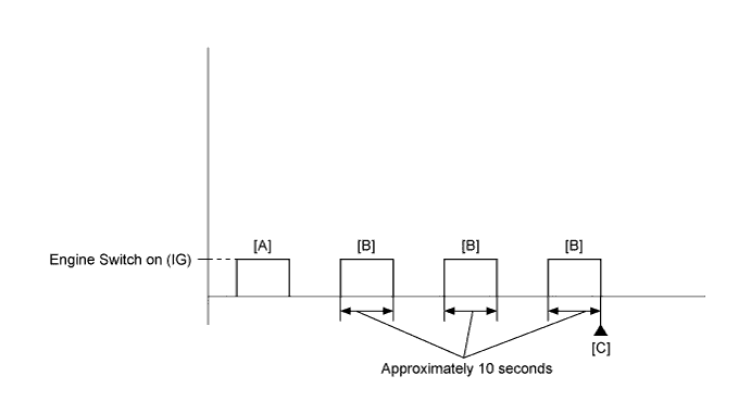
Turn the engine switch on (IG) and turn the GTS on [A].
-
Enter the following menus: Powertrain / Engine and ECT / Data List / All Data / Coolant Temp.
Tech Tips
-
Check DTC P2004 at a coolant temperature of 30°C (86°F) or less.
-
Check DTC P2006 at a coolant temperature of 80°C (176°F) or higher.
-
-
Turn the engine switch off.
-
Turn the engine switch on (IG), wait approximately 10 seconds, and then turn the engine switch off. Repeat this procedure 3 times [B].
-
Enter the following menus: Powertrain / Engine and ECT / Trouble Codes [C].
-
Read Pending DTCs.
Tech Tips
-
If a pending DTC is output, the system is malfunctioning.
-
If a pending DTC is not output, perform the following procedure.
-
-
Enter the following menus: Powertrain / Engine and ECT / Utility / All Readiness.
-
Input the DTC: P2004 or P2006.
-
Check the DTC judgment result.
GTS Display Description NORMAL
-
DTC judgment completed
-
System normal
ABNORMAL
-
DTC judgment completed
-
System abnormal
INCOMPLETE
-
DTC judgment not completed
-
Perform driving pattern after confirming DTC enabling conditions
N/A
-
Unable to perform DTC judgment
-
Number of DTCs which do not fulfill DTC preconditions has reached ECU's memory limit
Tech Tips
-
If the judgment result shows NORMAL, the system is normal.
-
If the judgment result shows ABNORMAL, the system has a malfunction.
-
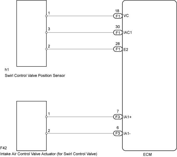
WIRING DIAGRAM
INSPECTION PROCEDURE
Tech Tips
Read freeze frame data using the GTS. The ECM records vehicle and driving condition information as freeze frame data the moment a DTC is stored. When troubleshooting, freeze frame data can help determine if the vehicle was moving or stationary, if the engine was warmed up or not, if the air fuel ratio was lean or rich, and other data from the time the malfunction occurred.
PROCEDURE
-
CHECK ANY OTHER DTCS OUTPUT (IN ADDITION TO DTC P2004 OR P2006)
-
Connect the GTS to the DLC3.
-
Turn the engine switch on (IG).
-
Turn the GTS on.
-
Enter the following menus: Powertrain / Engine and ECT / Trouble Codes.
-
Read the DTCs.
Result Result Proceed to DTC P2004 or P2006 is output A DTC P2004 or P2006 and other DTCs are output B Tech Tips
If any DTCs other than P2004 or P2006 are output, troubleshoot those DTCs first.
B 
GO TO DTC CHART Click here
A 
-
-
INSPECT INTAKE MANIFOLD (SWIRL CONTROL VALVE OPERATION)
-
Inspect the intake manifold Click here.
NG
REPLACE INTAKE MANIFOLD Click here
OK
-
-
CHECK HARNESS AND CONNECTOR (ECM - INTAKE AIR CONTROL VALVE ACTUATOR)
-
Disconnect the ECM connector.
-
Disconnect the intake air control valve actuator connector.
-
Measure the resistance according to the value(s) in the table below.
Standard Resistance Tester Connection Condition Specified Condition F3-6 (IA1-) - F42-2 Always Below 1 Ω F3-7 (IA1+) - F42-1 Always Below 1 Ω F3-6 (IA1-) or F42-2 - Body ground Always 10 kΩ or higher F3-7 (IA1+) or F42-1 - body ground Always 10 kΩ or higher -
Reconnect the ECM connector.
-
Reconnect the intake air control valve actuator connector.
NG
REPAIR OR REPLACE HARNESS OR CONNECTOR
OK
-
-
CHECK WHETHER DTC OUTPUT RECURS (DTC P2004 OR P2006)
-
Connect the GTS to the DLC3.
-
Turn the engine switch on (IG).
-
Turn the GTS on.
-
Clear the DTCs Click here.
-
Turn the engine switch off and wait for at least 30 seconds.
-
Turn the engine switch on (IG).
-
Turn the GTS on.
-
Drive the vehicle in accordance with the driving pattern described in the Confirmation Driving Pattern.
-
Enter the following menus: Powertrain / Engine and ECT / Trouble Codes / Pending.
-
Read the pending DTCs.
Result Result Proceed to DTC P2004 or P2006 are output A DTC is not output B
B
CHECK FOR INTERMITTENT PROBLEMS Click here
A 
REPLACE ECM Click here
-