SFI SYSTEM, Diagnostic DTC:P0088

| DTC Code | DTC Name |
|---|---|
| P0088 | Fuel Rail / System Pressure - Too High |
DESCRIPTION
The high-pressure fuel system consists of the spill valve, pump plunger, check valve, relief valve and fuel pressure sensor. The spill valve opens and closes the low-pressure fuel line (from the fuel tank), the pump plunger operated by the camshaft pressurizes fuel, the check valve mechanically opens and closes the high pressure fuel line (to the fuel delivery pipe), the relief valve prevents fuel pressure from becoming extremely high, and the fuel pressure sensor located on the fuel delivery pipe monitors fuel pressure.
The high-pressure side fuel pump is installed to the cylinder head cover (bank 1) and is driven by the cam located at the rear end of the exhaust camshaft.
When the plunger moves up and down due to camshaft rotation, it produces vacuum to suck fuel and pressurizes the fuel. This fuel then pushes the check valve open and flows into the fuel delivery pipe. The ECM opens and closes the spill valve to regulate the fuel pressure to the target fuel pressure of 4 to 13 MPa (40.8 to 132.6 kgf/cm2, 580 to 1886 psi). In order to obtain and maintain the target pressure, the ECM monitors the fuel pressure using the fuel pressure sensor and performs the feedback control.
If the internal fuel pressure of the fuel delivery pipe exceeds the standard pressure of 15.3 MPa (156.0 kgf/cm2, 2219 psi), the fuel relief valve installed on the gateway of the fuel delivery pipe discharges the fuel pressure and then returns the fuel back to the fuel tank.
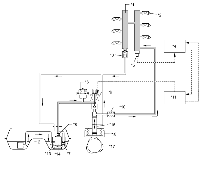
| *1 | Fuel Delivery Pipe | *2 | Fuel Injector |
| *3 | Relief Valve (15.3 MPa [156.0 kgf/cm2, 2219 psi]) |
*4 | ECM |
| *5 | Fuel Pressure Sensor | *6 | Pulsation Damper |
| *7 | Pressure Regulator (400 kPa [4.1 kgf/cm2, 58 psi]) |
*8 | Fuel Filter |
| *9 | Spill Valve | *10 | Check Valve (60 kPa [0.6 kgf/cm2, 8.7 psi]) |
| *11 | Injector Driver (EDU) | *12 | Fuel Tank |
| *13 | Jet Pump | *14 | Fuel Pump for Low Pressure |
| *15 | Pump Plunger | *16 | Fuel Pump for High Pressure |
| *17 | Exhaust Camshaft | - | - |
| DTC No. | DTC Detection Condition | Trouble Area |
|---|---|---|
| P0088 | ECM did not command that the high pressure side fuel pump opens spill valve, but fuel pressure increases 3 MPa (30.6 kgf/cm2, 435 psi) from target fuel pressure for about 10 seconds (1 trip detection logic) |
|
MONITOR DESCRIPTION
If the fuel pressure does not decrease even after the ECM commands the high-pressure fuel pump to open the spill control valve, a DTC is output.
If there is minimal difference between the fuel pressure before and after the fuel relief valve operates, a DTC is output.
MONITOR STRATEGY
| Required sensors/components | Fuel pressure sensor |
| Frequency of operation | Continuous |
CONFIRMATION DRIVING PATTERN
-
Connect the GTS to the DLC3.
-
Turn the engine switch on (IG) and turn the GTS on.
-
Record the Freeze Frame Data.
-
Clear the DTCs (even if no DTCs are stored, perform the clear DTC procedure) Click here.
-
Turn the engine switch off and wait for at least 30 seconds.
-
Turn the engine switch on (IG) and turn the GTS on.
-
Based on engine speed, engine load and other freeze frame data stored in the ECM, reproduce the conditions present when the DTC was stored.
-
Enter the following menus: Powertrain / Engine and ECT / Trouble Codes.
-
Read Pending DTCs.
Tech Tips
-
If a pending DTC is output, the system is malfunctioning.
-
If a pending DTC is not output, perform the following procedure.
-
-
Enter the following menus: Powertrain / Engine and ECT / Utility / All Readiness.
-
Input the DTC: P0088.
-
Check the DTC judgment result.
Tester Display Description NORMAL
-
DTC judgment completed
-
System normal
ABNORMAL
-
DTC judgment completed
-
System abnormal
INCOMPLETE
-
DTC judgment not completed
-
Perform driving pattern after confirming DTC enabling conditions
N/A
-
Unable to perform DTC judgment
-
Number of DTCs which do not fulfill DTC preconditions has reached ECU's memory limit
Tech Tips
-
If the judgment result shows NORMAL, the system is normal.
-
If the judgment result shows ABNORMAL, the system has a malfunction.
-
WIRING DIAGRAM
Refer to DTC P0190 Click here.
INSPECTION PROCEDURE
Tech Tips
Read freeze frame data using the GTS. The ECM records vehicle and driving condition information as freeze frame data the moment a DTC is stored. When troubleshooting, freeze frame data can help determine if the vehicle was moving or stationary, if the engine was warmed up or not, if the air fuel ratio was lean or rich, and other data from the time the malfunction occurred.
PROCEDURE
-
CHECK OTHER DTCS OUTPUT (IN ADDITION TO DTC P0088)
-
Connect the GTS to the DLC3.
-
Turn the engine switch on (IG) and turn the GTS on.
-
Enter the following menus: Powertrain / Engine and ECT / Trouble Codes.
-
Read the DTCs.
Result Result Proceed to DTC P0088 is output A DTC P0088 and other DTCs are output B Tech Tips
If any DTCs other than P0088 are output, troubleshoot those DTCs first.
B 
GO TO DTC CHART Click here
A 
-
-
CHECK FUEL PRESSURE SENSOR
-
Connect the GTS to the DLC3.
-
Start the engine and turn the GTS on.
-
Enter the following menus: Powertrain / Engine and ECT / Data List / Fuel Press.
-
Check that the fuel pressure fluctuates when the engine is raced.
OK Fuel pressure fluctuates.
NG
REPLACE FUEL PRESSURE SENSOR Click here
OK
-
-
REPLACE FUEL PUMP FOR HIGH PRESSURE
-
Replace the fuel pump for high pressure Click here.
NEXT
-
-
CHECK IF DTC OUTPUT RECURS (SEE IF DTC P0088 IS OUTPUT AGAIN)
-
Connect the GTS to the DLC3.
-
Turn the engine switch on (IG) and turn the GTS on.
-
Clear the DTCs Click here.
-
Drive the vehicle in accordance with the driving pattern described in the Confirmation Driving Pattern.
-
Enter the following menus: Powertrain / Engine and ECT / Trouble Codes.
-
Read the DTCs.
Result Result Proceed to DTC P0088 is output A DTC is not output B
B
END
A
-
-
INSPECT FUEL RELIEF VALVE
-
Connect the GTS to the DLC3.
-
Turn the engine switch on (IG) and turn the GTS on.
-
Enter the following menus: Powertrain / Engine and ECT / Data List / Fuel Press.
-
Start the engine.
-
Check the fuel pressure.
Result Tester Display Result Proceed to Fuel Press Below 15300 kPa (156 kgf/cm2, 2219 psi)
A 15300 kPa (156 kgf/cm2, 2219 psi) or more
B
B
REPLACE FUEL RELIEF VALVE Click here
A 
REPLACE ECM Click here
-