VEHICLE STABILITY CONTROL SYSTEM, Diagnostic DTC:C1432

| DTC Code | DTC Name |
|---|---|
| C1432 | Steering Angle Sensor Power Source Voltage Malfunction |
DESCRIPTION
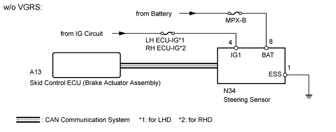
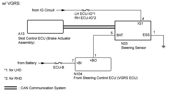
Signals from the steering sensor are sent to the skid control ECU (built into the brake actuator assembly) through CAN communication.
| DTC Code | DTC Detection Condition | Trouble Area |
|---|---|---|
| C1432 | When the voltage at terminal IG1 is between 9.5 and 17.4 V, a steering sensor power supply malfunction signal is received from the steering sensor. |
|
WIRING DIAGRAM
INSPECTION PROCEDURE
Note
Inspect the fuses for circuits related to this system before performing the following inspection procedure.
Tech Tips
-
When DTC U0073, U0123, U0124 and/or U0126 is output together with DTC C1432, inspect and repair the trouble areas indicated by DTC U0073, U0123, U0124 and/or U0126 first Click here.
-
When the speed sensor or the yaw rate sensor has trouble, DTCs for the steering sensor may be stored even when the steering sensor is normal. When DTCs for the speed sensor or yaw rate sensor are output together with DTCs for the steering sensor, inspect and repair the speed sensor and yaw rate sensor first, and then inspect and repair the steering sensor.
PROCEDURE
-
CHECK HARNESS AND CONNECTOR (IG1/ESS TERMINAL)
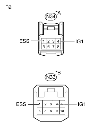
Text in Illustration *A w/o VGRS *B w/ VGRS *a Front view of wire harness connector
(to Steering Sensor)
-
Disconnect the steering sensor connector.
-
Measure the voltage according to the value(s) in the table below.
Standard Voltage w/o VGRS Tester Connection Switch Condition Specified Condition N34-4 (IG1) - Body ground Engine switch on (IG) 11 to 14 V w/ VGRS Tester Connection Switch Condition Specified Condition N33-4 (IG1) - Body ground Engine switch on (IG) 11 to 14 V -
Measure the resistance according to the value(s) in the table below.
Standard Resistance w/o VGRS Tester Connection Condition Specified Condition N34-1 (ESS) - Body ground Always Below 1 Ω w/ VGRS Tester Connection Condition Specified Condition N33-1 (ESS) - Body ground Always Below 1 Ω Result Result Proceed to NG A OK (w/o VGRS) B OK (w/ VGRS) C
B 
CHECK HARNESS AND CONNECTOR (BAT TERMINAL) Click here
C
CHECK HARNESS AND CONNECTOR (BAT TERMINAL) Click here
A 
REPAIR OR REPLACE HARNESS OR CONNECTOR
-
-
CHECK HARNESS AND CONNECTOR (BAT TERMINAL)
-
Disconnect the steering sensor connector.
-
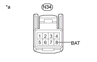
Text in Illustration *a Front view of wire harness connector
(to Steering Sensor)
Measure the voltage according to the value(s) in the table below.
Standard Voltage Tester Connection Condition Specified Condition N34-8 (BAT) - Body ground Always 11 to 14 V
NG 
REPAIR OR REPLACE HARNESS OR CONNECTOR
OK
REPLACE STEERING SENSOR Click here
-
-
CHECK HARNESS AND CONNECTOR (BAT TERMINAL)
-
Disconnect the steering sensor connector.
-
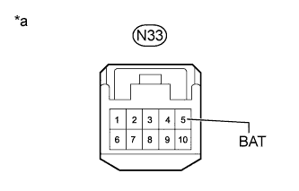
Text in Illustration *a Front view of wire harness connector
(to Steering Sensor)
Measure the voltage according to the value(s) in the table below.
Standard Voltage Tester Connection Condition Specified Condition N33-5 (BAT) - Body ground Always 11 to 14 V
NG
CHECK HARNESS AND CONNECTOR (STEERING SENSOR - FRONT STEERING CONTROL ECU) Click here
OK
REPLACE STEERING SENSOR Click here
-
-
CHECK HARNESS AND CONNECTOR (STEERING SENSOR - FRONT STEERING CONTROL ECU)
-
Disconnect the N33 steering sensor connector.
-
Disconnect the N104 front steering control ECU connector.
-
Measure the resistance according to the value(s) in the table below.
Standard Resistance Tester Connection Condition Specified Condition N33-5 (BAT) - N104-1 (+BO) Always Below 1 Ω N33-5 (BAT) - Body ground Always 10 kΩ or higher
NG
REPAIR OR REPLACE HARNESS OR CONNECTOR
OK 
-
-
CHECK HARNESS AND CONNECTOR (BATTERY - FRONT STEERING CONTROL ECU)
-
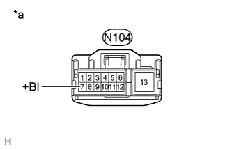
Text in Illustration *a Front view of wire harness connector
(to Front Steering Control ECU)
Disconnect the front steering control ECU connector.
-
Measure the voltage according to the value(s) in the table below.
Standard Voltage Tester Connection Condition Specified Condition N104-7 (+BI) - Body ground Always 11 to 14 V
NG
REPAIR OR REPLACE HARNESS OR CONNECTOR
OK
REPLACE FRONT STEERING CONTROL ECU Click here
-