SFI SYSTEM Pattern Select Switch Snow Mode Circuit
DESCRIPTION
When SNOW is selected, the operation of the throttle motor is moderated to control engine output.
This helps to reduce skidding of the drive wheels, and assists with takeoff acceleration, driving straightness and turning stability.
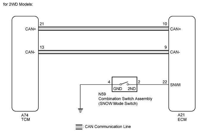
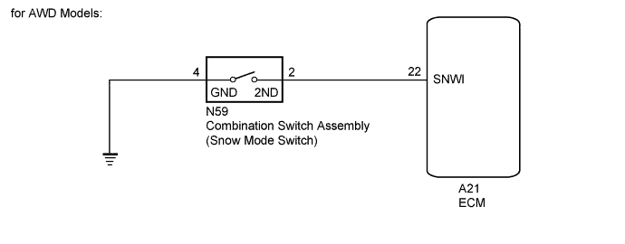
WIRING DIAGRAM
INSPECTION PROCEDURE
PROCEDURE
-
READ VALUE USING GTS (SNOW SWITCH STATUS)
-
Connect the GTS to the DLC3.
-
Turn the engine switch on (IG) and turn the GTS on.
-
Enter the following menus: Powertrain / Engine and ECT / Data List / Snow Switch Status.
-
Read the value displayed on the GTS.
OK Condition GTS Display (Snow Switch Status) SNOW mode switch pushed and held ON SNOW mode switch not pushed OFF
NG 
INSPECT COMBINATION SWITCH ASSEMBLY Click here
OK 
CHECK INTERMITTENT PROBLEMS
-
-
INSPECT COMBINATION SWITCH ASSEMBLY
-
Inspect the combination switch assembly (SNOW mode switch).
for 2WD model Click here
for AWD model Click here
Result Result Proceed to OK A NG (for 2WD model) B NG (for AWD model) C
B 
REPLACE COMBINATION SWITCH ASSEMBLY Click here
C
REPLACE COMBINATION SWITCH ASSEMBLY Click here
A 
-
-
CHECK HARNESS AND CONNECTOR (ECM - COMBINATION SWITCH ASSEMBLY)
-
Disconnect the combination switch assembly connector.
-
Disconnect the ECM connector.
-
Measure the resistance according to the value(s) in the table below.
Standard Resistance Tester Connection Condition Specified Condition A21-22 (SNWI) - N59-2 (2ND) Always Below 1 Ω A21-22 (SNWI) or N59-2 (2ND) - Body ground Always 10 kΩ or higher
NG
REPAIR OR REPLACE HARNESS OR CONNECTOR
OK
-
-
CHECK HARNESS AND CONNECTOR (COMBINATION SWITCH ASSEMBLY - BODY GROUND)
-
Disconnect the combination switch assembly connector.
-
Measure the resistance according to the value(s) in the table below.
Standard Resistance Tester Connection Condition Specified Condition N59-4 (GND) - Body ground Always Below 1 Ω
NG
REPAIR OR REPLACE HARNESS OR CONNECTOR
OK
REPLACE ECM Click here
-