SFI SYSTEM Starter Signal Circuit
DESCRIPTION
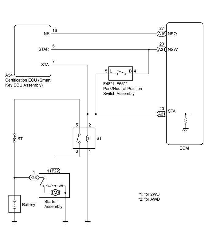
While the engine is being cranked, current flows from terminal STAR of the certification ECU (smart key ECU assembly) to the park/neutral position switch and also flows to terminal STA of the ECM (STA signal).
WIRING DIAGRAM
INSPECTION PROCEDURE
Note
Inspect the fuses for circuits related to this system before performing the following inspection procedure.
Tech Tips
This inspection procedure is based on the premise that the engine can crank normally. If the engine cannot crank normally, proceed to the problem symptoms table Click here.
PROCEDURE
-
READ VALUE USING GTS (STARTER SIGNAL)
-
Connect the GTS to the DLC3.
-
Turn the engine switch on (IG).
-
Turn the GTS on.
-
Enter the following menus: Powertrain / Engine and ECT / Data List / Starter Signal.
-
Read the value.
OK Engine Switch Position Starter Signal On (IG) Close (Starter signal OFF) START Open (Starter signal ON)
NG 
INSPECT PARK/NEUTRAL POSITION SWITCH ASSEMBLY Click here
OK 
PROCEED TO NEXT SUSPECTED AREA SHOWN IN PROBLEM SYMPTOMS TABLE Click here
-
-
INSPECT PARK/NEUTRAL POSITION SWITCH ASSEMBLY
-
Inspect the park/neutral position switch assembly (for 2WD) Click here.
-
Inspect the park/neutral position switch assembly (for AWD) Click here.
Result Result Proceed to OK A NG (for 2WD) B NG (for AWD) C
B 
REPLACE PARK/NEUTRAL POSITION SWITCH ASSEMBLY Click here
C
REPLACE PARK/NEUTRAL POSITION SWITCH ASSEMBLY Click here
A 
-
-
CHECK HARNESS AND CONNECTOR (PARK/NEUTRAL POSITION SWITCH - ECM)
-
Disconnect the park/neutral position switch connector.
-
Disconnect the ECM connector.
-
Measure the resistance according to the value(s) in the table below.
Standard Resistance (Check for Open) Tester Connection Condition Specified Condition F48-5 - A21-20 (STA) Always Below 1 Ω Standard Resistance (Check for Short) Tester Connection Condition Specified Condition F48-5 or A21-20 (STA) - Body ground Always 10 kΩ or higher
NG
REPAIR OR REPLACE HARNESS OR CONNECTOR
OK
GO TO SMART ACCESS SYSTEM WITH PUSH-BUTTON START Click here
-