SFI SYSTEM, Diagnostic DTC:P0705

| DTC Code | DTC Name |
|---|---|
| P0705 | Transmission Range Sensor Circuit Malfunction (PRNDL Input) |
DESCRIPTION
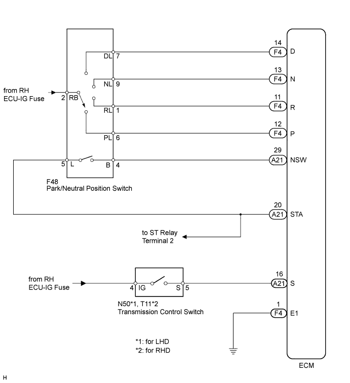
The park/neutral position switch detects the shift lever position and sends signals to the ECM.
Tech Tips
-
This DTC P0705 applicable to 2WD models only.
-
For AWD models, refer to automatic transmission system Click here.
| DTC No. | DTC Detection Condition | Trouble Area |
|---|---|---|
| P0705 | One of the following conditions 1, 2 or 3 is met (2 trip detection logic):
|
|
MONITOR DESCRIPTION
These DTCs indicate a problem with the park/neutral position switch and the wire harness in the park/neutral position switch circuit.
The park/neutral position switch detects the shift lever position and sends a signal to the ECM.
For security, the park/neutral position switch detects the shift lever position so that engine can be started only when the shift lever is in the P or N position.
The park/neutral position switch sends a signal to the ECM according to the shift position (P, R, N, D or M). The ECM determines that there is a problem with the switch or related parts if it receives more than 1 position signal simultaneously. The ECM will turn on the MIL and store the DTC.
MONITOR STRATEGY
| Required sensors/Components | Park/neutral position switch |
| Frequency of operation | Continuous |
CONFIRMATION DRIVING PATTERN
-
Connect the GTS to the DLC3.
-
Turn the engine switch on (IG) and turn the GTS on.
-
Clear the DTCs (even if no DTCs are stored, perform the clear DTC procedure) Click here.
-
Turn the engine switch off and wait for at least 30 seconds.
-
Turn the engine switch on (IG) and turn the GTS on.
-
Move the shift lever to R and wait 2 seconds or more.
-
Move the shift lever to N and wait 2 seconds or more.
-
Move the shift lever to D and wait 2 seconds or more.
-
Move the shift lever to M and wait 2 seconds or more.
-
Move the shift lever to P and wait 2 seconds or more.
-
Wait 1 minute or more.
-
Enter the following menus: Powertrain / Engine / Trouble Codes.
-
Read the pending DTCs.
Tech Tips
-
If a pending DTC is output, the system is malfunctioning.
-
If a pending DTC is not output, perform the following procedure.
-
-
Enter the following menus: Powertrain / Engine / Utility / All Readiness.
-
Input the DTC: P0705.
-
Check the DTC judgment result.
GTS Display Description NORMAL
-
DTC judgment completed
-
System normal
ABNORMAL
-
DTC judgment completed
-
System abnormal
INCOMPLETE
-
DTC judgment not completed
-
Perform driving pattern after confirming DTC enabling conditions
N/A
-
Unable to perform DTC judgment
-
Number of DTCs which do not fulfill DTC preconditions has reached ECU's memory limit
Tech Tips
-
If the judgment result shows NORMAL, the system is normal.
-
If the judgment result shows ABNORMAL, the system has a malfunction.
-
WIRING DIAGRAM
INSPECTION PROCEDURE
-
DATA LIST
Tech Tips
Using the GTS to read the Data List allows the values or states of switches, sensors, actuators and other items to be read without removing any parts. This non-intrusive inspection can be very useful because intermittent conditions or signals may be discovered before parts or wiring is disturbed. Reading the Data List information early in troubleshooting is one way to save diagnostic time.
Note
In the table below, the values listed under "Normal Condition" are reference values. Do not depend solely on these reference values when deciding whether a part is faulty or not.
-
Warm up the engine.
-
Turn the engine switch off.
-
Connect the GTS to the DLC3.
-
Turn the engine switch on (IG).
-
Turn the GTS on.
-
Enter the following menus: Powertrain / Engine / Data List /
-
According to the display on the GTS.
Tester Display Measurement Item/Range Normal Condition Diagnostic Note Shift SW Status (R Range) PNP switch status/
ON or OFF
-
Shift lever in R: ON
-
Shift lever not in R: OFF
When shift lever position displayed on the GTS differs from actual position, adjustment of PNP switch or shift cable may be incorrect Shift SW Status (P Range) PNP switch status/
ON or OFF
-
Shift lever in P: ON
-
Shift lever not in P: OFF
When shift lever position displayed on the GTS differs from actual position, adjustment of PNP switch or shift cable may be incorrect Shift SW Status (N Range) PNP switch status/
ON or OFF
-
Shift lever in N: ON
-
Shift lever not in N: OFF
When shift lever position displayed on the GTS differs from actual position, adjustment of PNP switch or shift cable may be incorrect Shift SW Status (D Range) PNP switch status/
ON or OFF
-
Shift lever in D or M: ON
-
Shift lever not in D or M: OFF
When shift lever position displayed on the GTS differs from actual position, adjustment of PNP switch or shift cable may be incorrect Sports Mode Selection SW Sport Mode Select Switch Status/
ON or OFF
-
Shift lever in M: ON
-
Shift lever not in M: OFF
- -
-
PROCEDURE
-
READ VALUE USING GTS
-
Connect the GTS to the DLC3.
-
Turn the engine switch on (IG).
-
Turn the GTS on.
-
Enter the following menus: Powertrain / Engine / Data List /
-
According to the display on the GTS.
OK Tester Display Shift Lever Position Specified Condition Neutral Position SW Signal N → R → P ON → OFF → ON Shift SW Status (R Range) N → R OFF → ON Shift SW Status (P Range) P ON Shift SW Status (N Range) N ON Shift SW Status (D Range) N → D OFF → ON
NG 
CHECK HARNESS AND CONNECTOR (BATTERY - PARK/NEUTRAL POSITION SWITCH) Click here
OK 
-
-
READ VALUE USING GTS
-
Connect the GTS to the DLC3.
-
Turn the engine switch on (IG).
-
Turn the GTS on.
-
Enter the following menus: Powertrain / Engine / Data List /
-
According to the display on the GTS.
OK Tester Display Shift Lever Position Specified Condition Sports Mode Selection SW D → M OFF → ON
NG
INSPECT TRANSMISSION FLOOR SHIFT ASSEMBLY (TRANSMISSION CONTROL SWITCH) Click here
OK 
CHECK FOR INTERMITTENT PROBLEMS Click here
-
-
INSPECT TRANSMISSION FLOOR SHIFT ASSEMBLY (TRANSMISSION CONTROL SWITCH)
-
Inspect the transmission control switch Click here.
NG 
REPLACE TRANSMISSION FLOOR SHIFT ASSEMBLY (TRANSMISSION CONTROL SWITCH) Click here
OK
-
-
CHECK HARNESS AND CONNECTOR (ECM CONNECTOR - BODY GROUND)
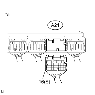
Text in Illustration *a Component without harness connected
(ECM)
-
Disconnect the A21 ECM connector.
-
Turn the engine switch on (IG).
-
Measure the voltage according to the value(s) in the table below.
Standard Voltage Tester Connection Shift Lever Position Switch Condition Specified Condition A21-16 (S) - Body ground M Engine switch on (IG) 11 to 14 V* Not in M Engine switch on (IG) 0 to 1.5 V* Tech Tips
*: The voltage will drop slightly due to the turning on of the back-up light.
NG
REPAIR OR REPLACE HARNESS OR CONNECTOR
OK
REPLACE ECM Click here
-
-
CHECK HARNESS AND CONNECTOR (BATTERY - PARK/NEUTRAL POSITION SWITCH)
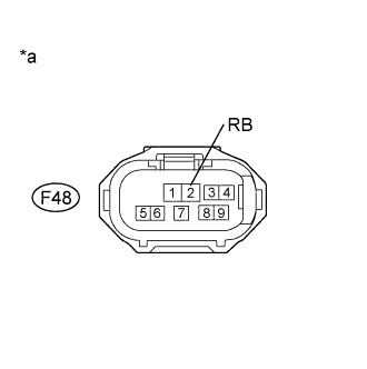
Text in Illustration *a Front view of wire harness connector
(to Park/neutral Position Switch)
-
Disconnect the F48 park/neutral position switch.
-
Turn the engine switch on (IG).
-
Measure the voltage according to the value(s) in the table below.
Standard Voltage Tester Connection Switch Condition Specified Condition F48-2 (RB) - Body ground Engine switch on (IG) 11 to 14 V
NG
REPAIR OR REPLACE HARNESS OR CONNECTOR
OK
-
-
INSPECT PARK/NEUTRAL POSITION SWITCH ASSEMBLY
-
Inspect the park/neutral position switch Click here.
NG
REPLACE PARK/NEUTRAL POSITION SWITCH ASSEMBLY Click here
OK
-
-
CHECK HARNESS AND CONNECTOR (ECM - PARK/NEUTRAL POSITION SWITCH)
-
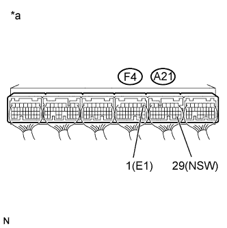
Text in Illustration *a Component with harness connected
(ECM)
Turn the engine switch on (IG).
-
Measure the voltage according to the value(s) in the table below.
Standard Voltage Tester Connection Shift Lever Position Switch Condition Specified Condition A21-29 (NSW) - F4-1 (E1) P or N Engine switch on (IG) 0 to 1.5 V Except P or N Engine switch on (IG) 11 to 14 V -
Turn the engine switch off.
-
Disconnect the F4 ECM connector.
-
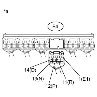
Text in Illustration *a Component without harness connected
(ECM)
Turn the engine switch on (IG).
-
Measure the voltage according to the value(s) in the table below.
Standard Voltage Tester Connection Shift Lever Position Switch Condition Specified Condition F4-12 (P) - F4-1 (E1) P Engine switch on (IG) 11 to 14 V Except P Engine switch on (IG) 0 to 1.5 V F4-11 (R) - F4-1 (E1) R Engine switch on (IG) 11 to 14 V Except R Engine switch on (IG) 0 to 1.5 V F4-13 (N) - F4-1 (E1) N Engine switch on (IG) 11 to 14 V Except N Engine switch on (IG) 0 to 1.5 V F4-14 (D) - F4-1 (E1) D Engine switch on (IG) 11 to 14 V Except D Engine switch on (IG) 0 to 1.5 V
NG
REPAIR OR REPLACE HARNESS OR CONNECTOR
OK
REPLACE ECM Click here
-