SFI SYSTEM, Diagnostic DTC:P1276, P1277, P1278, P1279, P127A, P127B

| DTC Code | DTC Name |
|---|---|
| P1276 | Port Injector Circuit No. 1 |
| P1277 | Port Injector Circuit No. 2 |
| P1278 | Port Injector Circuit No. 3 |
| P1279 | Port Injector Circuit No. 4 |
| P127A | Port Injector Circuit No. 5 |
| P127B | Port Injector Circuit No. 6 |
DESCRIPTION
The D-4S system has two injection systems. One is the in-cylinder direct injection system that directly injects pressurized fuel into the combustion chamber. The other is the intake port injection system. The ECM determines the percentage of in-cylinder direct injection to the intake port injection systems in accordance with the engine speed and load.
| DTC No. | DTC Detection Condition | Trouble Area |
|---|---|---|
| P1276 P1277 P1278 P1279 P127A P127B |
Current is not applied to the injector 10 times or more with the engine running. |
|
MONITOR DESCRIPTION
The ECM monitors the injection control of the port injector. If a malfunction is detected in the port injector circuit, the ECM cancels the injection control for the corresponding cylinder and turns on the MIL.
MONITOR STRATEGY
| Required sensors/Components | Port injector (cylinder 1 to 6) |
| Frequency of operation | Continuous |
CONFIRMATION DRIVING PATTERN
-
Connect the GTS to the DLC3.
-
Turn the engine switch on (IG) and turn the GTS on.
-
Clear the DTCs (even if no DTCs are stored, perform the clear DTC procedure) Click here.
-
Turn the engine switch off and wait for at least 30 seconds.
-
Turn the engine switch on (IG) and turn the GTS on.
-
Start the engine.
-
Idle the engine for 10 seconds [A].
-
Enter the following menus: Powertrain / Engine and ECT / Trouble Codes.
-
Read the DTCs [B].
Tech Tips
-
If a DTC is output, the system is malfunctioning.
-
If a DTC is not output, perform the following procedure.
-
-
Enter the following menus: Powertrain / Engine and ECT / Utility / All Readiness.
-
Input the DTC: P1276, P1277, P1278, P1279, P127A or P127B.
-
Check the DTC judgment result.
GTS Display Description NORMAL
-
DTC judgment completed
-
System normal
ABNORMAL
-
DTC judgment completed
-
System abnormal
INCOMPLETE
-
DTC judgment not completed
-
Perform driving pattern after confirming DTC enabling conditions
N/A
-
Unable to perform DTC judgment
-
Number of DTCs which do not fulfill DTC preconditions has reached ECU's memory limit
Tech Tips
-
If the judgment result shows ABNORMAL, the system has a malfunction.
-
If the judgment result shows NORMAL, the system is normal.
-
If the judgment result shows INCOMPLETE or N/A, perform steps [A] and [B] again.
-
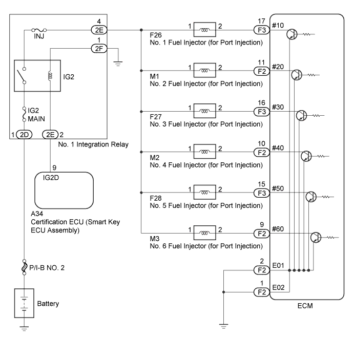
WIRING DIAGRAM
INSPECTION PROCEDURE
Tech Tips
Read freeze frame data using the GTS. The ECM records vehicle and driving condition information as freeze frame data the moment a DTC is stored. When troubleshooting, freeze frame data can help determine if the vehicle was moving or stationary, if the engine was warmed up or not, if the air fuel ratio was lean or rich, and other data from the time the malfunction occurred.
PROCEDURE
-
CHECK ANY OTHER DTCS OUTPUT (IN ADDITION TO DTC P1276, P1277, P1278, P1279, P127A OR P127B)
-
Connect the GTS to the DLC3.
-
Turn the engine switch on (IG).
-
Turn the GTS on.
-
Enter the following menus: Powertrain / Engine and ECT / Trouble Codes.
-
Read the DTCs.
Result Result Proceed to P1276, P1277, P1278, P1279, P127A or P127B is output A P1276, P1277, P1278, P1279, P127A and P127B are output B P1276, P1277, P1278, P1279, P127A or P127B and other DTCs are output C Tech Tips
If any DTCs other than P1276, P1277, P1278, P1279, P127A or P127B are output, troubleshoot those DTCs first.
B 
CHECK AND REPLACE INJ FUSE
C
GO TO DTC CHART Click here
A 
-
-
CHECK ECM TERMINAL VOLTAGE (#10, #20, #30, #40, #50 OR #60 TERMINAL)
-
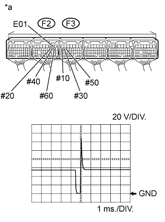
Text in Illustration *a Component with harness connected
(ECM)
Inspect using an oscilloscope.
-
While idling, check the waveform of the ECM connectors.
Standard Tester Connection Specified Condition F3-17 (#10) - F2-2 (E01)
F2-11 (#20) - F2-2 (E01)
F3-16 (#30) - F2-2 (E01)
F2-10 (#40) - F2-2 (E01)
F3-15 (#50) - F2-2 (E01)
F2-9 (#60) - F2-2 (E01)
Correct waveform appears as shown
NG 
CHECK FUEL INJECTOR FOR PORT INJECTION (POWER SOURCE VOLTAGE) Click here
OK 
CHECK FOR INTERMITTENT PROBLEMS Click here
-
-
CHECK FUEL INJECTOR FOR PORT INJECTION (POWER SOURCE VOLTAGE)
-
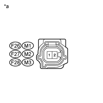
Text in Illustration *a Front view of wire harness connector
(to Fuel Injector for Port Injection)
Disconnect the fuel injector for port injection connector.
-
Turn the engine switch on (IG).
-
Measure the voltage according to the value(s) in the table below.
Standard Voltage Tester Connection Condition Specified Condition F26-1 - Body ground Engine switch on (IG) 11 to 14 V M1-1 - Body ground Engine switch on (IG) 11 to 14 V F27-1 - Body ground Engine switch on (IG) 11 to 14 V M2-1 - Body ground Engine switch on (IG) 11 to 14 V F28-1 - Body ground Engine switch on (IG) 11 to 14 V M3-1 - Body ground Engine switch on (IG) 11 to 14 V -
Reconnect the fuel injector for port injection connector.
NG
CHECK AND REPAIR HARNESS OR CONNECTOR (IG2 RELAY - INJECTOR FOR PORT INJECTION)
OK
-
-
CHECK HARNESS AND CONNECTOR (ECM - FUEL INJECTOR FOR PORT INJECTION)
-
Disconnect the ECM connector.
-
Disconnect the injector connector.
-
Measure the resistance according to the value(s) in the table below.
Standard Resistance (Check for Short) Tester Connection Condition Specified Condition F26-2 - F3-17 (#10) Always Below 1 Ω M1-2 - F2-11 (#20) Always Below 1 Ω F27-2 - F3-16 (#30) Always Below 1 Ω M2-2 - F2-10 (#40) Always Below 1 Ω F28-2 - F3-15 (#50) Always Below 1 Ω M3-2 - F2-9 (#60) Always Below 1 Ω Standard Resistance (Check for Short) Tester Connection Condition Specified Condition F26-2 or F3-17 (#10) - Body ground Always 10 kΩ or higher M1-2 or F2-11 (#20) - Body ground Always 10 kΩ or higher F27-2 or F3-16 (#30) - Body ground Always 10 kΩ or higher M2-2 or F2-10 (#40) - Body ground Always 10 kΩ or higher F28-2 or F3-15 (#50) - Body ground Always 10 kΩ or higher M3-2 or F2-9 (#60) - Body ground Always 10 kΩ or higher -
Reconnect the injector connector.
-
Reconnect the ECM connector.
NG
REPAIR OR REPLACE HARNESS OR CONNECTOR (ECM - FUEL INJECTOR FOR PORT INJECTION)
OK
-
-
CHECK FUEL INJECTOR FOR PORT INJECTION (RESISTANCE)
-
Check the fuel injector for port injection resistance Click here.
Tech Tips
Perform "Inspection After Repair" after replacing the fuel injector assembly (for port injection) Click here.
NG
REPLACE FUEL INJECTOR FOR PORT INJECTION Click here
OK
REPLACE ECM Click here
-