SFI SYSTEM, Diagnostic DTC:P0365, P0367, P0368, P0390, P0392, P0393

| DTC Code | DTC Name |
|---|---|
| P0365 | Camshaft Position Sensor "B" Circuit (Bank 1) |
| P0367 | Camshaft Position Sensor "B" Circuit Low Input (Bank 1) |
| P0368 | Camshaft Position Sensor "B" Circuit High Input (Bank 1) |
| P0390 | Camshaft Position Sensor "B" Circuit (Bank 2) |
| P0392 | Camshaft Position Sensor "B" Circuit Low Input (Bank 2) |
| P0393 | Camshaft Position Sensor "B" Circuit High Input (Bank 2) |
DESCRIPTION
The exhaust camshaft VVT sensors consist of a magnet and MRE (Magnetic Resistive Element).
The exhaust camshaft has a sensor plate with 3 teeth on its outer circumference.
When the exhaust camshaft rotates, changes occur in the air gaps between the 3 teeth and MRE, which affects the magnet. As a result, the resistance of the MRE material fluctuates. The VVT sensor converts the exhaust camshaft rotation data to pulse signals, uses the pulse signals to determine the camshaft angle, and sends it to the ECM.
The crank angle sensor plate has 34 teeth. The pickup coil generates 34 signals for each engine rotation. Based on combination of the VVT signals and NE signal, the ECM detects the crankshaft angle. Then the ECM uses this data to control fuel injection time and injection timing. Also, based on the NE signal, the ECM detects the engine speed.
| DTC No. | DTC Detection Condition | Trouble Area |
|---|---|---|
| P0365 P0390 |
No VVT sensor signal to ECM at engine speed of 600 rpm or more (1 trip detection logic) |
|
| P0367 P0392 |
Output voltage of VVT sensor for exhaust side (bank 1, 2) less than 0.3 V for 4 seconds (1 trip detection logic) |
|
| P0368 P0393 |
Output voltage of VVT sensor for exhaust side (bank 1, 2) more than 4.7 V for 4 seconds (1 trip detection logic) |
|
Reference: Inspection using an oscilloscope
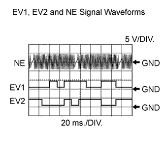
Tech Tips
-
The correct waveform is as shown in the illustration.
-
The wavelength becomes shorter as the engine speed increases.
-
EV1+ and EV2+ stand for the VVT sensor for exhaust side signal, and NE+ stands for the crankshaft position sensor signal.
Item Content ECM Terminal Names Between EV1+ and EV1-, or EV2+ and EV2-
Between NE+ and NE-
Tester Range 5 V/DIV., 20 ms./DIV. Condition Idling
MONITOR DESCRIPTION
If no signal is transmitted by the VVT sensor despite the engine running, or the rotations of the camshaft and the crankshaft are not synchronized, the ECM interprets this as a malfunction of the sensor.
When the sensor output voltage remains less than 0.3 V or more than 4.7 V for more than 5 seconds, the ECM sets a DTC.
MONITOR STRATEGY
| Required sensors/Components (Main) | VVT sensor for exhaust side (bank 1 and 2) |
| Required sensors/Components (Related) | Crankshaft position sensor |
| Frequency of operation | Continuous |
CONFIRMATION DRIVING PATTERN
-
Connect the GTS to the DLC3.
-
Turn the engine switch on (IG) and turn the GTS on.
-
Clear the DTCs (even if no DTCs are stored, perform the clear DTC procedure) Click here.
-
Turn the engine switch off and wait for at least 30 seconds.
-
Turn the engine switch on (IG) and turn the GTS on.
-
Start the engine.
-
Idle the engine for 10 seconds or more [A].
-
Enter the following menus: Powertrain / Engine and ECT / Trouble Codes / Pending.
-
Read Pending DTCs [B].
Tech Tips
-
If a pending DTC is output, the system is malfunctioning.
-
If a pending DTC is not output, perform the following procedure.
-
-
Enter the following menus: Powertrain / Engine and ECT / Utility / All Readiness.
-
Input the DTC: P0365, P0367, P0368, P0390, P0392 or P0393.
-
Check the DTC judgment result.
GTS Display Description NORMAL
-
DTC judgment completed
-
System normal
ABNORMAL
-
DTC judgment completed
-
System abnormal
INCOMPLETE
-
DTC judgment not completed
-
Perform driving pattern after confirming DTC enabling conditions
N/A
-
Unable to perform DTC judgment
-
Number of DTCs which do not fulfill DTC preconditions has reached ECU's memory limit
Tech Tips
-
If the judgment result shows NORMAL, the system is normal.
-
If the judgment result shows ABNORMAL, the system has a malfunction.
-
If the judgment result shows INCOMPLETE or N/A, perform steps [A] and [B] again.
-
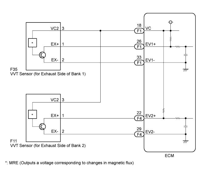
WIRING DIAGRAM
INSPECTION PROCEDURE
Tech Tips
-
Bank 1 refers to the bank that includes the No. 1 cylinder*.
*: The No. 1 cylinder is the cylinder which is farthest from transmission.
-
Bank 2 refers to the bank that does not include the No. 1 cylinder.
-
Read freeze frame data using the GTS The ECM records vehicle and driving condition information as freeze frame data the moment a DTC is stored. When troubleshooting, freeze frame data can help determine if the vehicle was moving or stationary, if the engine was warmed up or not, if the air fuel ratio was lean or rich, and other data from the time the malfunction occurred.
-
If no problem is found by this diagnostic troubleshooting procedure, troubleshoot the engine mechanical system.
PROCEDURE
-
CHECK VVT SENSOR FOR EXHAUST SIDE (SENSOR POWER SOURCE)
-
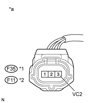
Text in Illustration *1 Bank 1 *2 Bank 2 *a Front view of wire harness connector
(to VVT Sensor for Exhaust Side)
Disconnect the VVT sensor for exhaust side connector.
-
Turn the engine switch on (IG).
-
Measure the voltage according to the value(s) in the table below.
Standard Voltage Tester Connection Switch Condition Specified Condition F35-3 (VC2) - Body ground Engine switch on (IG) 4.5 to 5.5 V F11-3 (VC2) - Body ground Engine switch on (IG) 4.5 to 5.5 V -
Reconnect the VVT sensor connector.
NG 
CHECK HARNESS AND CONNECTOR (VVT SENSOR FOR EXHAUST SIDE - ECM) Click here
OK 
-
-
CHECK HARNESS AND CONNECTOR (VVT SENSOR FOR EXHAUST SIDE - ECM)
-
Disconnect the VVT sensor connector.
-
Disconnect the ECM connector.
-
Measure the resistance according to the value(s) in the table below.
Standard Resistance (Check for Open) Tester Connection Condition Specified Condition F35-1 (EX+) - F1-26 (EV1+) Always Below 1 Ω F35-2 (EX-) - F1-33 (EV1-) Always Below 1 Ω F11-1 (EX+) - F4-22 (EV2+) Always Below 1 Ω F11-2 (EX-) - F4-29 (EV2-) Always Below 1 Ω Standard Resistance (Check for Short) Tester Connection Condition Specified Condition F35-1 (EX+) or F1-26 (EV1+) - Body ground Always 10 kΩ or higher F35-2 (EX-) or F1-33 (EV1-) - Body ground Always 10 kΩ or higher F11-1 (EX+) or F4-22 (EV2+) - Body ground Always 10 kΩ or higher F11-2 (EX-) or F4-29 (EV2-) - Body ground Always 10 kΩ or higher -
Reconnect the VVT sensor connector.
-
Reconnect the ECM connector.
NG 
REPAIR OR REPLACE HARNESS OR CONNECTOR (VVT SENSOR FOR EXHAUST SIDE - ECM)
OK
-
-
CHECK SENSOR INSTALLATION (VVT SENSOR FOR EXHAUST SIDE)
-
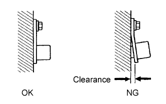
Check the VVT sensor installation.
OK Sensor is installed correctly.
NG
SECURELY REINSTALL VVT SENSOR FOR EXHAUST SIDE Click here
OK
-
-
CHECK EXHAUST CAMSHAFT
-
Check the teeth of the timing rotor.
OK Camshaft timing rotor does not have any cracks or deformation. Tech Tips
Perform "Inspection After Repair" after replacing the exhaust camshaft Click here.
NG
REPLACE EXHAUST CAMSHAFT Click here
OK
-
-
CHECK VALVE TIMING (CHECK FOR LOOSE TIMING CHAIN AND JUMPED TEETH)
-
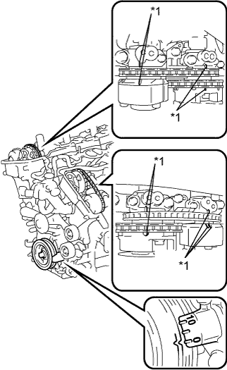
Text in Illustration *1 Timing Mark Remove the cylinder head cover sub-assemblies RH and LH.
-
Turn the crankshaft to align the timing marks of the crankshaft.
-
Align the notch of the crankshaft pulley to the "0" position.
-
Check if the timing marks of the camshaft pulley and camshaft bearing cap align.
-
Turn the crankshaft clockwise 360° if the timing marks do not align. Check if they align once again.
OK The timing marks of the camshaft pulley and the camshaft bearing cap align when the notch of the crankshaft pulley is in the "0" position. -
Reinstall the cylinder head cover sub-assemblies RH and LH.
NG
CHECK ENGINE MECHANICAL SYSTEM Click here
OK
-
-
REPLACE VVT SENSOR FOR EXHAUST SIDE
-
Replace the VVT sensor for exhaust side Click here.
NEXT
-
-
CHECK WHETHER DTC OUTPUT RECURS (DTC P0365, P0367, P0368, P0390, P0392 OR P0393)
-
Connect the GTS to the DLC3.
-
Turn the engine switch on (IG).
-
Turn the GTS on.
-
Clear the DTCs Click here.
-
Turn the engine switch off and wait for at least 30 seconds.
-
Start the engine.
-
Turn the GTS on.
-
Drive the vehicle in accordance with the driving pattern described in the Confirmation Driving Pattern.
-
Enter the following menus: Powertrain / Engine and ECT / Trouble Codes / Pending.
-
Read the DTC.
Result Result Proceed to DTC is not output A DTC P0365, P0367, P0368, P0390, P0392 or P0393 is output B Tech Tips
If the engine does not start, replace the ECM.
B
REPLACE ECM Click here
A 
END
-
-
CHECK HARNESS AND CONNECTOR (VVT SENSOR FOR EXHAUST SIDE - ECM)
-
Disconnect the VVT sensor for exhaust side connector.
-
Disconnect the ECM connectors.
-
Measure the resistance according to the value(s) in the table below.
Standard Resistance (Check for Open) Tester Connection Condition Specified Condition F35-3 (VC2) - F1-18 (VC) Always Below 1 Ω F11-3 (VC2) - F1-18 (VC) Always Below 1 Ω Standard Resistance (Check for Short) Tester Connection Condition Specified Condition F35-3 (VC2) or F1-18 (VC) - Body ground Always 10 kΩ or higher F11-3 (VC2) or F1-18 (VC) - Body ground Always 10 kΩ or higher -
Reconnect the VVT sensor for exhaust side connector.
-
Reconnect the ECM connectors.
NG
REPAIR OR REPLACE HARNESS OR CONNECTOR (VVT SENSOR FOR EXHAUST SIDE - ECM)
OK
REPLACE ECM Click here
-