SFI SYSTEM, Diagnostic DTC:P0139, P013A, P013C, P0159

| DTC Code | DTC Name |
|---|---|
| P0139 | Oxygen Sensor Circuit Slow Response (Bank 1 Sensor 2) |
| P013A | Oxygen Sensor Slow Response - Rich to Lean Bank 1 Sensor 2 |
| P013C | Oxygen Sensor Slow Response - Rich to Lean Bank 2 Sensor 2 |
| P0159 | Oxygen Sensor Circuit Slow Response (Bank 2 Sensor 2) |
CAUTION / NOTICE / HINT
DESCRIPTION
Refer to DTC P0136 Click here.
| DTC No. | DTC Detection Condition | Trouble Area |
|---|---|---|
| P0139 P0159 |
Heated oxygen sensor voltage does not drop to below 0.2 V immediately after fuel cut status (2 trip detection logic) |
|
| P013A P013C |
The heated oxygen sensor voltage does not drop from 0.35 V to 0.2 V immediately after fuel cut starts (1 trip detection logic) |
|
MONITOR DESCRIPTION
-
Heated Oxygen Sensor Output Voltage During Fuel Cut (P0139 or P0159)
The sensor output voltage drops to below 0.2 V (extremely lean status) immediately when the vehicle decelerates and fuel cut is operating. If the voltage does not drop to below 0.2 V when accumulated intake air mass is more than 16 g, the system determines that the sensor response has deteriorated, illuminates the MIL and stores a DTC.
-
Abnormal Voltage Output of Heated Oxygen Sensor during Fuel Cut from Rich Condition (P013A and P013C)
If the sensor output voltage does not drop from 0.35 to 0.2 V immediately when the vehicle decelerates and fuel cut is operating, the ECM illuminates the MIL and stores a DTC.
MONITOR STRATEGY
| Required Sensors/Components (Main) | Heated oxygen sensor (sensor 2) |
| Frequency of Operation | Once per driving cycle: Heated oxygen sensor abnormal voltage during fuel cut |
| Duration | 7 seconds |
TYPICAL ENABLING CONDITIONS
| Engine coolant temperature | 75°C (167°F) or more |
| Estimated catalyst temperature | 620°C (1148°F) or more |
| Fuel-cut | On |
| Battery voltage | 11 V or more |
| Engine coolant temperature | 75°C (167°F) or more |
| Estimated catalyst temperature | 620°C (1148°F) or more |
| Fuel-cut | On |
TYPICAL MALFUNCTION THRESHOLDS
| Total airflow volume reached after start of fuel-cut while heated oxygen sensor voltage remains at 0.2 V or higher | More than 16 g |
| Duration until rear heated oxygen sensor voltage drops from 0.35 V to 0.2 V during fuel cut (Normalized) | 1 second or more |
CONFIRMATION DRIVING PATTERN
Tech Tips
-
This confirmation driving pattern is used in the "Perform Confirmation Driving Pattern" procedure of the following diagnostic troubleshooting procedure.
-
Performing this confirmation driving pattern will activate the heated oxygen sensor monitor (The catalyst monitor is performed simultaneously). This is very useful for verifying the completion of a repair.
-
-
Connect the GTS to the DLC3.
-
Turn the engine switch on (IG).
-
Turn the GTS on.
-
Clear the DTCs (even if no DTCs are stored, perform the clear DTC procedure) Click here.
-
Turn the engine switch off and wait for at least 30 seconds.
-
Turn the engine switch on (IG) and turn the GTS on.
-
Enter the following menus: Powertrain / Engine and ECT / Monitor / Current Monitor.
-
Check that Catalyst Efficiency / Current is Incomplete.
-
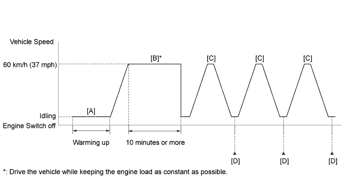
Start the engine and warm it up until the engine coolant temperature is 75°C (167°F) or higher with the shift lever in P [A].
Tech Tips
In order to keep the idling stable, turn off the A/C and all other electric loads and do not perform any shift operations.
-
Drive the vehicle at approximately 60 km/h (37 mph) for 10 minutes or more [B].
CAUTION:
When performing the confirmation driving pattern, obey all speed limits and traffic laws.
Tech Tips
Drive the vehicle while keeping the engine load as constant as possible.
-
With the shift lever in M, drive the vehicle at 60 km/h (37 mph), and then decelerate the vehicle by releasing the accelerator pedal for 5 seconds or more to perform the fuel-cut [C].
CAUTION:
When performing the confirmation driving pattern, obey all speed limits and traffic laws.
-
Enter the following menus: Powertrain / Engine and ECT / Monitor / Current Monitor / O2 Sensor / RL F/C B1S2, RL F/C B2S2 [D].
-
Check the Test Value for RL F/C B1S2, RL F/C B2S2.
Tech Tips
If Test Value displays 0, perform step [C] until it displays a value larger than 0, as the O2 sensor monitor is not finished.
-
Repeat step [C] 2 times or more in one driving cycle.
-
Enter the following menus: Powertrain / Engine and ECT / Trouble Codes / Pending.
-
Read the pending DTCs [D].
Tech Tips
-
If a pending DTC is output, the system is malfunctioning.
-
If a pending DTC is not output, perform the following procedure.
-
-
Enter the following menus: Powertrain / Engine and ECT / Utility / All Readiness.
-
Input the DTC: P0139, P013A, P013C or P0159.
-
Check the DTC judgment result.
GTS Display Description NORMAL
-
DTC judgment completed
-
System normal
ABNORMAL
-
DTC judgment completed
-
System abnormal
INCOMPLETE
-
DTC judgment not completed
-
Perform driving pattern after confirming DTC enabling conditions
N/A
-
Unable to perform DTC judgment
-
Number of DTCs which do not fulfill DTC preconditions has reached ECU memory limit
Tech Tips
-
If the judgment result shows NORMAL, the system is normal.
-
If the judgment result shows ABNORMAL, the system has a malfunction.
-
If the judgment result shows INCOMPLETE or N/A, drive the vehicle with the shift lever in M, and then perform step [C] again.
-
WIRING DIAGRAM
Refer to DTC P0136 Click here.
INSPECTION PROCEDURE
Note
Inspect the fuses for circuits related to this system before performing the following inspection procedure.
Tech Tips
-
Bank 1 refers to the bank that includes the No. 1 cylinder*.
*: The No. 1 cylinder is the cylinder which is farthest from transmission.
-
Bank 2 refers to the bank that does not include the No. 1 cylinder.
-
Sensor 1 refers to the sensor closest to the engine assembly.
-
Sensor 2 refers to the sensor farthest away from the engine assembly.
-
Read freeze frame data using the GTS. The ECM records vehicle and driving condition information as freeze frame data the moment a DTC is stored. When troubleshooting, freeze frame data can help determine if the vehicle was moving or stationary, if the engine was warmed up or not, if the air fuel ratio was lean or rich, and other data from the time the malfunction occurred.
PROCEDURE
-
CHECK FOR EXHAUST GAS LEAK
-
Check for exhaust gas leak.
OK No gas leakage. Tech Tips
Perform "Inspection After Repair" after replacing the exhaust system Click here.
B 
REPAIR OR REPLACE HARNESS OR CONNECTOR (HEATED OXYGEN SENSOR - ECM)
A 
-
-
CHECK HARNESS AND CONNECTOR (CHECK FOR SHORT)
-
Turn the engine switch off and wait for 5 minutes.
-
Disconnect the ECM connector.
-
Measure the resistance according to the value(s) in the table below.
Standard Resistance (Bank 1 Sensor 2) Tester Connection Condition Specified Condition A21-4 (HT1B) - A21-26 (OX1B) Always 10 kΩ or higher Standard Resistance (Bank 2 Sensor 2) Tester Connection Condition Specified Condition A21-3 (HT2B) - A21-27 (OX2B) Always 10 kΩ or higher -
Reconnect the ECM connector.
NG
REPAIR OR REPLACE HARNESS OR CONNECTOR
OK
-
-
PERFORM CONFIRMATION DRIVING PATTERN
-
Perform the Confirmation Driving Pattern (P0139, P013A, P013C and P0159).
NEXT
-
-
READ DTC OUTPUT (DTC P0139, P013A, P013C OR P0159 IS OUTPUT AGAIN)
-
Connect the GTS to the DLC3.
-
Turn the engine switch on (IG).
-
Turn the GTS on.
-
Enter the following menus: Powertrain / Engine and ECT / Utility / All Readiness.
-
Input DTCs: P0139, P013A, P013C or P0159.
-
Check that the DTC monitor is NORMAL. If the monitor is INCOMPLETE, perform the driving pattern and but increase vehicle speed.
Result Result Proceed to NORMAL (DTC is not output) A ABNORMAL (DTC P0139, P013A, P013C or P0159 is output) B Tech Tips
Perform "Inspection After Repair" after replacing the heated oxygen sensor Click here.
B
REPLACE HEATED OXYGEN SENSOR Click here
A 
CHECK FOR INTERMITTENT PROBLEMS Click here
-