VEHICLE STABILITY CONTROL SYSTEM, Diagnostic DTC:C120B

| DTC Code | DTC Name |
|---|---|
| C120B | IG Supply Voltage Low |
DESCRIPTION
| DTC Code | DTC Detection Condition | Trouble Area |
|---|---|---|
| C120B | The voltage at terminal IG1 is currently 8.4 V or less or there is a record of the voltage being 8.4 V or less, and there is a master cylinder pressure sensor output malfunction for 0.2 seconds or more. |
|
WIRING DIAGRAM
Refer to DTC C1241 Click here.
INSPECTION PROCEDURE
Note
When replacing the brake actuator assembly, perform zero point calibration and store system information Click here.
PROCEDURE
-
CHECK HARNESS AND CONNECTOR (IG1 CIRCUIT)
-
Disconnect the skid control ECU (brake actuator assembly) connector.
-
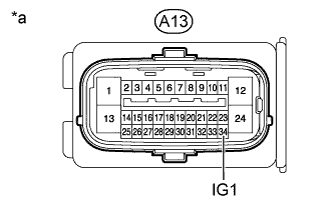
Text in Illustration *a Front view of wire harness connector
(to Skid Control ECU [Brake Actuator Assembly])
Measure the voltage according to the value(s) in the table below.
Standard Voltage Tester Connection Switch Condition Specified Condition A13-34 (IG1) - Body ground Engine switch on (IG) 11 to 14 V Result Result Proceed to OK A NG (for 2GR-FSE) B NG (for 4GR-FSE) C
B 
CHECK OR REPLACE CHARGING SYSTEM OR BATTERY Click here
C
CHECK OR REPLACE CHARGING SYSTEM OR BATTERY Click here
A 
-
-
RECONFIRM DTC
-
Clear the DTCs Click here.
-
Turn the engine switch off.
-
Check for DTC Click here.
Result Result Proceed to DTC is not output A DTC is output B
B
REPLACE BRAKE ACTUATOR ASSEMBLY Click here
A 
CHECK FOR INTERMITTENT PROBLEMS Click here
-