TIRE PRESSURE WARNING INITIATOR DRIVER (for LHD) REMOVAL

-
PRECAUTION
CAUTION:
Be sure to read Precaution thoroughly before servicing Click here.
Note
After turning the engine switch off, waiting time may be required before disconnecting the cable from the negative (-) battery terminal. Therefore, make sure to read the disconnecting the cable from the negative (-) battery terminal notice before proceeding with work Click here.
-
DISCONNECT CABLE FROM NEGATIVE BATTERY TERMINAL
CAUTION:
Wait at least 90 seconds after disconnecting the cable from the negative (-) battery terminal to disable the SRS system.
Note
When disconnecting the cable, some systems need to be initialized after the cable is reconnected Click here.
-
REMOVE CENTER INSTRUMENT CLUSTER FINISH PANEL
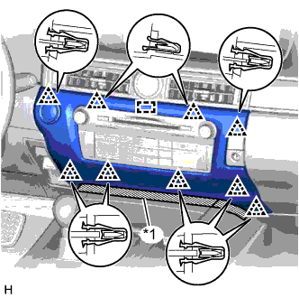
Text in Illustration *1 Protective Tape
-
Put protective tape around the center instrument cluster finish panel.
-
Detach the 9 clips and guide.
-
Disconnect the connector and remove the center instrument cluster finish panel.
-
-
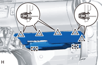
REMOVE INSTRUMENT PANEL FINISH PANEL END RH
Text in Illustration *1 Protective Tape
-
Put protective tape around the instrument panel finish panel end RH.
-
Detach the 5 clips and 2 guides and remove the instrument panel finish panel end RH.
-
-
REMOVE FRONT DOOR SCUFF PLATE RH
Tech Tips
Use the same procedure described for the LH side.
-
REMOVE FRONT DOOR OPENING TRIM COVER RH
Tech Tips
Use the same procedure described for the LH side.
-
REMOVE INSTRUMENT SIDE PANEL RH
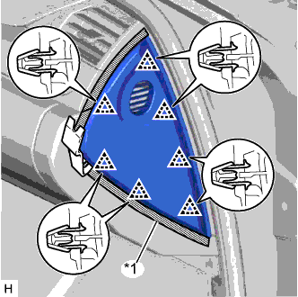
Text in Illustration *1 Protective Tape
-
Put protective tape around the instrument side panel RH.
-
Using a moulding remover, detach the 7 clips and remove the instrument side panel RH.
-
w/ Airbag Cut Off Switch:
-
Disconnect the connector.
-
-
-
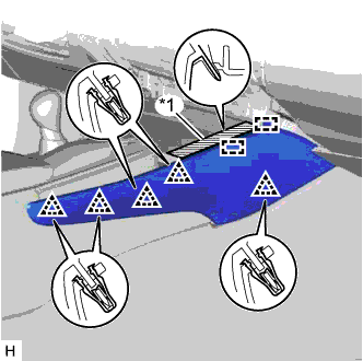
REMOVE NO. 2 INSTRUMENT PANEL UNDER COVER SUB-ASSEMBLY
-
Detach the 5 clips and 2 guides.
-
Disconnect the connectors, detach the clamp and remove the No. 2 instrument panel under cover sub-assembly.
-
-
REMOVE GLOVE COMPARTMENT DOOR ASSEMBLY
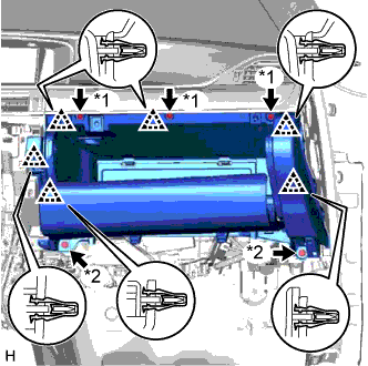
Text in Illustration *1 Screw <A> *2 Bolt <E>
-
Remove the 3 screws <A> and 2 bolts <E>.
-
Detach the 6 clips.
-
Disconnect the connectors, detach the clamp and remove the glove compartment door assembly.
-
-
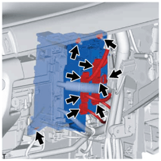
REMOVE COWL SIDE JUNCTION BLOCK RH
-
w/ VGRS System:
-
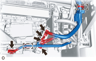
Disconnect the 5 connectors.
-
Using a clip remover, detach the 2 clamps.
-
-
for AWD:
-
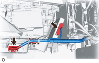
Disconnect the 2 connectors.
-
Using a clip remover, detach the clamp.
-
-
w/o VGRS System:
-
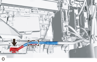
Disconnect the connector.
-
Using a clip remover, detach the clamp.
-
-
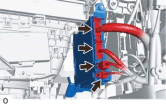
Disconnect the 4 connectors.
-
Remove the bolt and nut.
-
Remove the cowl side junction block RH from the reinforcement.
-
-
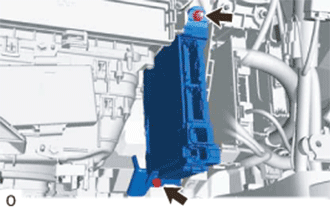
REMOVE ECU INTEGRATION BOX RH
-
Disconnect all the connectors.
-
Remove the 2 nuts, bolt and ECU integration box RH.
-
-
REMOVE TIRE PRESSURE MONITOR INITIATOR DRIVER
-
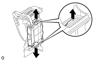
Detach the 2 claws and remove the tire pressure monitor initiator driver.
-