FRONT SUSPENSION MEMBER (for AWD) INSTALLATION

-
INSTALL FRONT SUSPENSION CROSSMEMBER SUB-ASSEMBLY
-
TEMPORARILY TIGHTEN FRONT SUSPENSION LOWER ARM ASSEMBLY LH
-
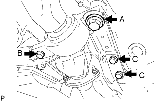
Install the front suspension lower arm and side rail plate with the 4 bolts.
- Torque:
- for bolt A
- 151 N*m { 1540 kgf*cm, 111 ft.*lbf }
- for bolt B
- 86 N*m { 877 kgf*cm, 63 ft.*lbf }
- for bolt C
- 50 N*m { 510 kgf*cm, 37 ft.*lbf }
-
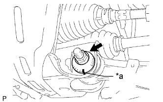
Text in Illustration *a Matchmark Insert the front suspension camber No. 1 from the front of the vehicle. Then install the front suspension camber No. 2 adjust cam and loosely tighten the nut.
Note
Align the matchmarks before installation.
Tech Tips
Fully tighten the nut after stabilizing the suspension.
-
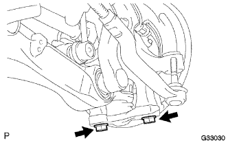
Install the front lower ball joint with the 2 bolts.
- Torque:
- 120 N*m { 1224 kgf*cm, 89 ft.*lbf }
-
-
TEMPORARILY TIGHTEN FRONT SUSPENSION LOWER ARM ASSEMBLY RH
Tech Tips
Remove the RH side following the same procedures as with the LH side.
-
INSTALL FRONT STABILIZER BAR
-
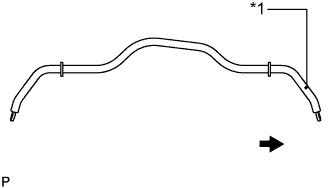
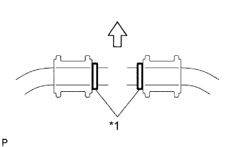
Text in Illustration *1 Identification Mark 
Right Side of the Vehicle Install the front stabilizer bar to the vehicle.
Note
The identification mark must be on the right side of the vehicle when installing the front stabilizer bar.
-
-
INSTALL FRONT NO. 1 STABILIZER BAR BUSH
-
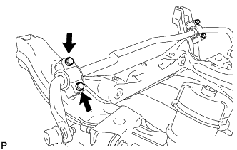
Text in Illustration *1 Bush Stopper 
Front Side of the Vehicle Install the 2 front No. 1 stabilizer bar bushes outside of the bush stoppers on the front stabilizer bar as shown in the illustration.
Note
Be sure to install the front No. 1 stabilizer bar bush so that the cutouts face the front of the vehicle.
-
-
INSTALL FRONT NO. 2 STABILIZER BRACKET LH
-
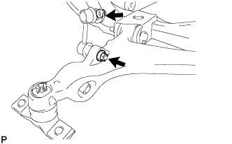
Install the front No. 2 stabilizer bracket LH on the vehicle with the 2 bolts.
- Torque:
- 78 N*m { 795 kgf*cm, 58 ft.*lbf }
-
-
INSTALL FRONT NO. 2 STABILIZER BRACKET RH
Tech Tips
Remove the RH side following the same procedures as with the LH side.
-
INSTALL FRONT STABILIZER LINK ASSEMBLY LH
-
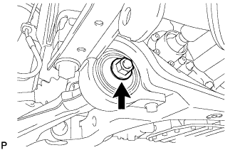
Install the front stabilizer link assembly LH with the 2 nuts.
- Torque:
- 84 N*m { 857 kgf*cm, 62 ft.*lbf }
-
-
INSTALL FRONT STABILIZER LINK ASSEMBLY RH
Tech Tips
Remove the RH side following the same procedures as with the LH side.
-
INSTALL POWER STEERING LINK ASSEMBLY
-
Install the power steering link assembly with the 2 bolts, 2 washers and 2 nuts.
- Torque:
- 102 N*m { 1038 kgf*cm, 75 ft.*lbf }
-
Connect the wire harness connectors to the power steering link assembly.
-
-
INSTALL ENGINE AND TRANSMISSION ASSEMBLY
-
STABILIZE SUSPENSION
-
Install the front wheels.
- Torque:
- 103 N*m { 1050 kgf*cm, 76 ft.*lbf }
-
Lower the vehicle and bounce it up and down several times to stabilize the front suspension.
-
Remove the front wheels.
-
Jack up the front suspension lower arm placing a wooden block in between. Apply a load to the front suspension so that the front suspension lower arm is placed in a horizontal position.
-
-
TIGHTEN FRONT SUSPENSION LOWER ARM ASSEMBLY LH
-
Text in Illustration *a Matchmark Fully tighten the bolt on the front of the front suspension lower arm.
- Torque:
- 119 N*m { 1213 kgf*cm, 88 ft.*lbf }
Note
Align the matchmarks before installation.
-
Fully tighten the installation nut of the lower arm No. 2 bracket sub-assembly.
- Torque:
- 113 N*m { 1152 kgf*cm, 83 ft.*lbf }
-
-
TIGHTEN FRONT SUSPENSION LOWER ARM ASSEMBLY RH
Tech Tips
Remove the RH side following the same procedures as with the LH side.