FRONT SHOCK ABSORBER (for AWD) REMOVAL

-
REMOVE FRONT WHEEL
-
SEPARATE FRONT SPEED SENSOR
-

Remove the 3 bolts and separate the front speed sensor from the steering knuckle and front shock absorber with coil spring.
Note
Be careful not to deform the bracket of the front shock absorber with coil spring when removing the bolt.
-
-
SEPARATE FRONT SUSPENSION UPPER ARM ASSEMBLY
-
Remove the clip and castle nut.
-
Install 2 spacers (SST spacer B) to the front suspension upper arm assembly so that there is a space of approximately 1 mm (0.0394 in.) between the arm and spacers.
- SST
- 09960-20010 ( 09961-02060 )
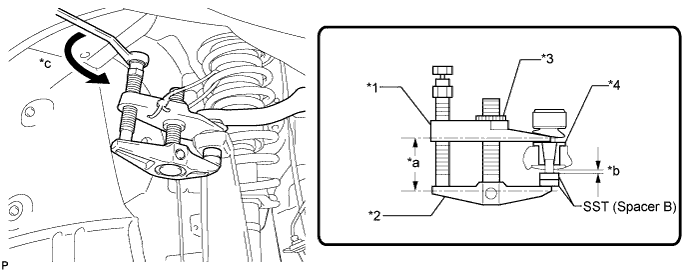
Text in Illustration *1 Claw *2 Body *3 Nut *4 Spacer *a Parallel *b Space of approx. 1 mm *c Turn - - Note
-
Be sure to install the spacers (SST spacer B) as the steering knuckle spacer may shift.
-
As SST may become damaged, make sure the space between the arm and spacers is not less than 1 mm (0.0394 in.).
-
Using SST, separate the front suspension upper arm from the steering knuckle.
- SST
- 09960-20010 ( 09961-02010 )
CAUTION:
Apply grease to the threads and end of the SST bolt.
Note
-
Do not damage the dust cover.
-
As the dust cover may be damaged, adjust SST with the center nut so that the body and claw are parallel.
-
Be sure to tie the string of SST to the vehicle to prevent SST from dropping.
-
-
SEPARATE TIE ROD ASSEMBLY
-
Remove the clip and castle nut.
-
Install 2 spacers (SST spacer B) to the tie rod assembly LH so that there is a space of approximately 1 mm (0.0397 in.) between the arm and spacers.
- SST
- 09960-20010 ( 09961-02060 )
Note
-
Be sure to install the spacers (SST spacer B) as the steering knuckle spacer may shift.
-
As SST may become damaged, make sure the space between the arm and spacers is not 1 mm (0.0397 in.) or less.
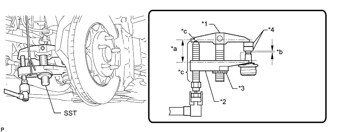
Text in Illustration *1 Body *2 Claw *3 Nut *4 Spacer B *a Parallel *b 1 mm (0.0397 in.) *c Molybdenum Grease Application Area - - -
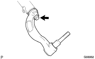
Using SST, disconnect the tie rod assembly from the steering knuckle.
- SST
- 09960-20010 ( 09961-02060 )
CAUTION:
Apply grease molybdenum grease to the bolt threads and the tip of SST.
Note
-
Do not damage the dust cover.
-
As the dust cover may be damaged, adjust SST with the center nut so that the body and claw are parallel.
-
Make sure to tie the string of SST to the vehicle to prevent SST from dropping.
-
-
REMOVE UPPER SHOCK ABSORBER CAP (w/ AVS)
-
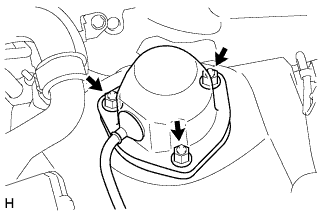
Remove the 3 nuts and upper shock absorber cap.
-
Disconnect the connector.
-
-
REMOVE ABSORBER CONTROL ACTUATOR (w/ AVS)
-
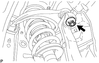
Turn the absorber control actuator counterclockwise 40° to remove it from the front shock absorber with coil spring.
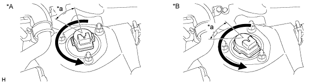
Text in Illustration *A 2WD *B AWD *a 40° - -
-
-
REMOVE FRONT SHOCK ABSORBER WITH COIL SPRING
-
Support the front suspension lower arm with a jack.
Note
Be sure to place a wooden block between the jack and the front suspension lower arm to avoid damage.
-
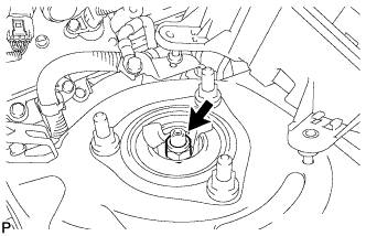
Remove the nut and front shock absorber upper bracket plate.
Note
Insert the front shock absorber bracket lower to secure the front shock absorber with coil spring.
-
Loosen the lock nut of the front shock absorber.
Note
-
Do not remove the lock nut.
-
Loosen the lock nut only when disassembling the front shock absorber with coil spring.
-
-
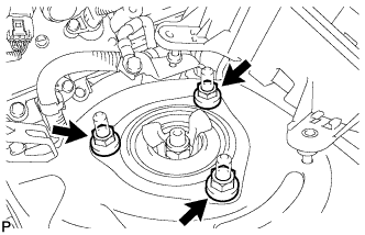
Remove the 3 nuts from the upper side of the front suspension support.
-
Slowly lower the jack.
-
Remove the bolt from the lower side to remove the front shock absorber with coil spring and front No. 3 spring support reinforcement.
-
-
REMOVE FRONT SHOCK ABSORBER ASSEMBLY
-
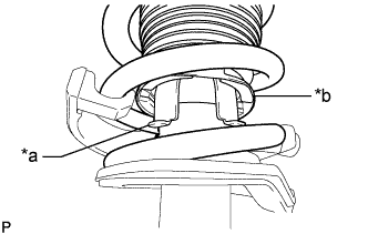
Text in Illustration *a Claw of Front Shock Absorber Assembly LH *b End of Front Coil Spring Upper Insulator LH Disconnect the end of the front coil spring upper insulator LH from the claw of the front shock absorber assembly LH.
-
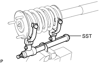
Secure SST in a vise.
- SST
- 09727-30021 ( 09727-00010, 09727-00021, 09727-00031 )
-
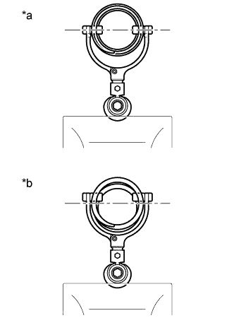
Text in Illustration *a Correct *b Incorrect Attach the arm of SST to the diameter of the coil spring.
CAUTION:
-
Make sure that the coil spring is installed so that the distance between the upper and lower hooks of SST is at the maximum.
-
Make sure that the claws of the hooks are securely attached.
-
-
Using SST, compress the coil spring.
CAUTION:
-
If the coil spring bends during the compression, immediately stop the compression and reinstall SST.
-
Do not compress the spring until the coil springs contact each other.
-
Do not use an impact wrench.
-
-
Confirm that the coil spring becomes free and remove the lock nut.
CAUTION:
Do not remove the lock nut when the coil spring is not free.
-
Remove the actuator support bracket (w/ AVS).
-
Remove the front suspension support sub-assembly with front coil spring upper insulator.
-
Remove the front coil spring insulator upper from the front suspension support sub-assembly.
-
Remove the front spring bumper from the front suspension support sub-assembly.
-
-
Remove the front coil spring and SST.
Note
Do not use an impact wrench. It will damage the SST.
-
Remove the front coil spring insulator lower.
-
-
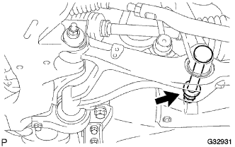
REMOVE FRONT SHOCK ABSORBER LOWER BRACKET
-
Remove the bolt from the front shock absorber lower bracket.
-