REAR COIL SPRING INSTALLATION

-
INSTALL REAR UPPER SPRING SEAT
-
Install the rear upper spring seat to the vehicle with the 3 bolts.
- Torque:
- 57 N*m { 581 kgf*cm, 42 ft.*lbf }
-
-
INSTALL REAR COIL SPRING
-
Install the rear lower coil spring insulator to the rear No. 2 suspension arm.
-
Install the rear upper coil spring insulator to the rear coil spring.
-
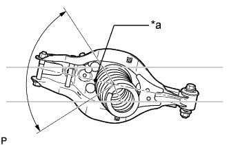
Text in Illustration *a Identification Mark Temporarily install the rear coil spring to the rear No. 2 suspension arm.
Note
Make sure that the identification mark is positioned towards the lower and outer sides of the vehicle.
-
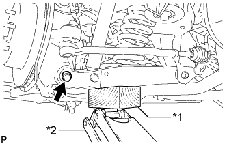
Text in Illustration *1 Wooden Block *2 Jack Using a jack and wooden block, raise the vehicle gradually to install the rear No. 2 suspension arm to the rear axle carrier. Then temporarily install the bolt and nut.
Note
-
Insert the bolt with the threaded end facing the rear of the vehicle.
-
When jacking up the rear No. 2 suspension arm assembly, be sure to jack it up slowly.
-
Do not jack up the rear No. 2 suspension arm assembly too high as the vehicle may fall.
-
Make sure to perform this operation with the vehicle kept as low as possible.
-
-
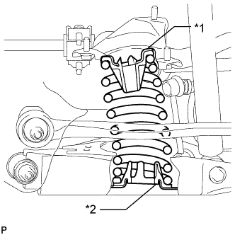
Text in Illustration *1 Rear Upper Coil Spring Insulator *2 Rear Lower Coil Spring Insulator Check that the rear upper coil spring insulator and rear lower coil spring insulator are installed as shown in the illustration.
-
-
TEMPORARILY INSTALL REAR SHOCK ABSORBER ASSEMBLY
-
Temporarily install the rear shock absorber assembly to the rear No. 2 suspension arm with the bolt and nut.
Note
Insert the bolt with the threaded end facing the rear of the vehicle.
-
-
INSTALL REAR STABILIZER LINK ASSEMBLY
-
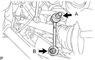
Install the rear stabilizer link assembly with the 2 nuts.
- Torque:
- for nut A
- 89 N*m { 908 kgf*cm, 66 ft.*lbf }
- for nut B
- 70 N*m { 714 kgf*cm, 52 ft.*lbf }
Tech Tips
If the ball joint turns together with the nut, use a 6 mm hexagon wrench to hold the stud bolt.
-
-
TEMPORARILY INSTALL REAR NO. 1 SUSPENSION ARM ASSEMBLY
-
Temporarily install the rear No. 1 suspension arm assembly to the rear axle assembly with the bolt and nut.
-
-
CONNECT TOE CONTROL LINK SUB-ASSEMBLY (w/o DYNAMIC REAR STEERING)
-
Connect the toe control link sub-assembly to the rear axle assembly with a new nut.
- Torque:
- 70 N*m { 714 kgf*cm, 52 ft.*lbf }
-
-
CONNECT REAR STEERING LINK ASSEMBLY (w/ DYNAMIC REAR STEERING)
-
Connect the rear steering link assembly to the rear axle assembly with a new nut.
- Torque:
- 70 N*m { 714 kgf*cm, 52 ft.*lbf }
-
-
STABILIZE SUSPENSION
-
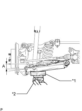
Text in Illustration *1 Wooden Block *2 Jack Jack up the rear No. 2 suspension arm assembly, placing a wooden block underneath to avoid damage. Apply load to the suspension so that the rear No. 2 suspension arm assembly is positioned as shown in the illustration.
Standard Length (A) 9.7 mm (0.3819 in.) Note
-
When jacking up the rear No. 2 suspension arm assembly, be sure to jack it up slowly.
-
Do not jack up the rear No. 2 suspension arm assembly too high as the vehicle may fall.
-
Make sure to perform this operation with the vehicle kept as low as possible.
-
-
-
TIGHTEN REAR SHOCK ABSORBER ASSEMBLY
-
Tighten the bolt of the rear shock absorber.
- Torque:
- 110 N*m { 1122 kgf*cm, 81 ft.*lbf }
Note
Since a stopper nut is used, tighten the bolt.
-
-
TIGHTEN REAR NO. 1 SUSPENSION ARM ASSEMBLY
-
Tighten the bolt of the rear No. 1 suspension arm assembly.
- Torque:
- 90 N*m { 918 kgf*cm, 66 ft.*lbf }
-
-
TIGHTEN REAR NO. 2 SUSPENSION ARM ASSEMBLY
-
Tighten the nut of the rear No. 2 suspension arm assembly for the suspension member side.
- Torque:
- 150 N*m { 1530 kgf*cm, 111 ft.*lbf }
-
Tighten the bolt of the rear No. 2 suspension arm assembly for the rear axle assembly side.
- Torque:
- 145 N*m { 1479 kgf*cm, 107 ft.*lbf }
-
-
INSTALL REAR SUSPENSION ARM COVER
-
Install the rear suspension arm cover to the rear No. 2 suspension arm with the 3 bolts.
- Torque:
- 12 N*m { 122 kgf*cm, 9.0 ft.*lbf }
-
-
CONNECT REAR HEIGHT CONTROL SENSOR SUB-ASSEMBLY
-
Connect the rear height control sensor to the rear No. 1 upper control arm with the nut.
- Torque:
- 8.0 N*m { 82 kgf*cm, 71 in.*lbf }
-
-
INSTALL REAR WHEEL
- Torque:
- 103 N*m { 1050 kgf*cm, 76 ft.*lbf }
-
INSPECT AND ADJUST REAR WHEEL ALIGNMENT
-
HEADLIGHT AIMING ADJUSTMENT