REAR SHOCK ABSORBER INSTALLATION

-
INSTALL REAR NO. 1 SPRING BUMPER
-
Install the rear No. 1 spring bumper to the rear shock absorber assembly.
-
-
INSTALL REAR SUSPENSION SUPPORT ASSEMBLY
-
w/o AVS:
-
Install the rear suspension support assembly, rear No. 1 shock absorber cushion and rear No. 1 shock absorber cushion washer to the rear shock absorber assembly.
-
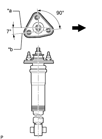
Text in Illustration *a Absorber Lower Bush Axis Line *b Rear Suspension Support Assembly Stud (Toward Vehicle Interior) 2-Point Axis Line 
Front of the Vehicle Align the rear suspension support assembly so that the studs are positioned as shown in the illustration.
-
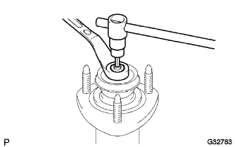
Using a 6 mm hexagon wrench, hold the piston rod of the rear shock absorber and tighten a new nut.
- Torque:
- 18 N*m { 184 kgf*cm, 13 ft.*lbf }
Note
Make sure that the socket hexagon wrench is fully inserted.
-
-
w/ AVS:
-
Install the rear suspension support assembly, rear No. 1 shock absorber cushion, rear No. 1 shock absorber cushion washer and actuator support bracket to the rear shock absorber assembly.
-
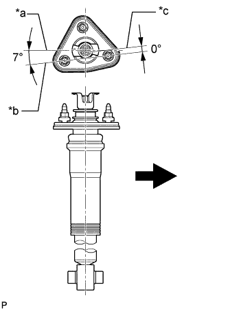
Text in Illustration *a Absorber Lower Bush Axis Line *b Rear Suspension Support Assembly Stud (Toward Vehicle Interior) 2-Point Axis Line *c Line Extending from Width Across Flats of Absorber Rod Front of the Vehicle Align the rear suspension support assembly so that the studs are positioned as shown in the illustration.
-
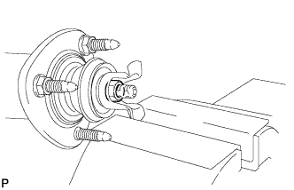
Hold the actuator support bracket and tighten a new nut.
- Torque:
- 18 N*m { 184 kgf*cm, 13 ft.*lbf }
Note
Hold the actuator support bracket so as not to deform it.
-
-
-
TEMPORARILY TIGHTEN REAR SHOCK ABSORBER ASSEMBLY
-
Install the 3 nuts to the upper side of the rear shock absorber.
- Torque:
- 74 N*m { 755 kgf*cm, 55 ft.*lbf }
-
Temporarily install the rear shock absorber assembly to the rear No. 2 suspension arm with the bolt and nut.
Note
Insert the bolt with the threaded end facing the rear of the vehicle.
-
-
INSTALL ABSORBER CONTROL ACTUATOR
-
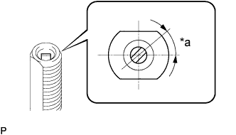
Text in Illustration *a 40° Check that the control rod of the rear shock absorber is in the position shown in the illustration.
Note
If the control rod is not in the position shown in the illustration, turn the control rod to adjust the position before installing the absorber control actuator.
-
Install the absorber control actuator to the actuator support bracket.
-

Text in Illustration *a 40° Turn the actuator clockwise approximately 40° until a click is felt.
Note
-
Before turning the actuator, make sure to check that the actuator output shaft and control rod are securely connected.
-
Do not turn the actuator more than 40°.
-
Do not drop the absorber control actuator. If it is dropped, replace it with a new one.
-
-
Connect the connector.
-
-
CONNECT TOE CONTROL LINK SUB-ASSEMBLY (w/o DYNAMIC REAR STEERING)
-
Connect the toe control link sub-assembly to the rear axle assembly with a new nut.
- Torque:
- 70 N*m { 714 kgf*cm, 52 ft.*lbf }
-
-
CONNECT REAR STEERING LINK ASSEMBLY (w/ DYNAMIC REAR STEERING)
-
Connect the rear steering link assembly to the rear axle assembly with a new nut.
- Torque:
- 70 N*m { 714 kgf*cm, 52 ft.*lbf }
-
-
STABILIZE SUSPENSION
-
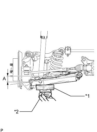
Text in Illustration *1 Wooden Block *2 Jack Jack up the rear No. 2 suspension arm assembly, and place a wooden block underneath to avoid damage. Apply load to the suspension so that the rear No. 2 suspension arm assembly is positioned as shown in the illustration.
Standard Length (A) 9.7 mm (0.3819 in.) Note
-
When jacking up the rear No. 2 suspension arm assembly, be sure to jack it up slowly.
-
Do not jack up the rear No. 2 suspension arm assembly too high as the vehicle may fall.
-
Make sure to perform this operation with the vehicle kept as low as possible.
-
-
-
TIGHTEN REAR SHOCK ABSORBER ASSEMBLY
-
Tighten the bolt of the rear shock absorber.
- Torque:
- 110 N*m { 1122 kgf*cm, 81 ft.*lbf }
Note
Since a stopper nut is used, tighten the bolt.
-
-
INSTALL REAR SUSPENSION ARM COVER
-
Install the rear suspension arm cover to the rear No. 2 suspension arm with the 3 bolts.
- Torque:
- 12 N*m { 122 kgf*cm, 9.0 ft.*lbf }
-
-
INSTALL REAR WHEEL
- Torque:
- 103 N*m { 1050 kgf*cm, 76 ft.*lbf }
-
INSTALL INNER LUGGAGE COMPARTMENT TRIM COVER
-
INSPECT AND ADJUST REAR WHEEL ALIGNMENT