REAR DIFFERENTIAL CARRIER ASSEMBLY (for 4GR-FSE) DISASSEMBLY

-
REMOVE REAR DIFFERENTIAL BREATHER PLUG
-
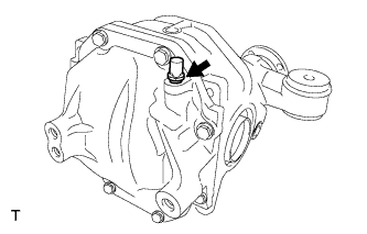
Remove the rear differential breather plug from the rear differential carrier cover.
-
-
REMOVE REAR DIFFERENTIAL CARRIER COVER
-
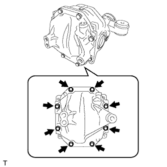
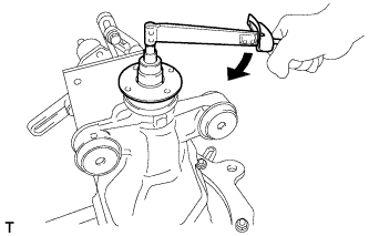
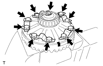
Remove the 8 bolts.
-
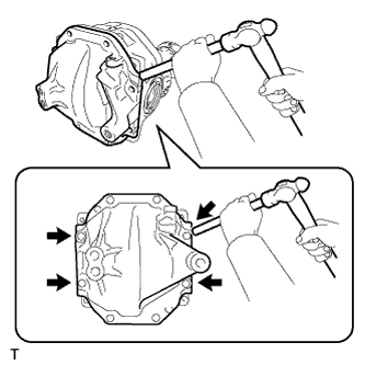
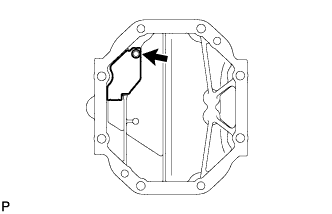
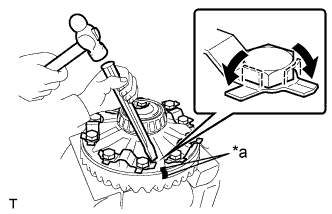
Using a brass bar and hammer, remove the rear differential carrier cover from the rear differential carrier.
Note
-
Place the brass bar onto the corners of the rear differential carrier cover.
-
Do not damage the sealing surface of the rear differential carrier.
-
-
-
REMOVE REAR DIFFERENTIAL CARRIER STRAIGHT PIN
-
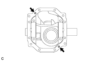
Remove the 2 rear differential carrier straight pins from the rear differential carrier.
-
-
REMOVE REAR DIFFERENTIAL BREATHER PLUG OIL DEFLECTOR
-
Remove the bolt and rear differential breather plug oil deflector from the rear differential carrier cover.
-
-
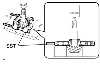
SECURE REAR DIFFERENTIAL CARRIER
-
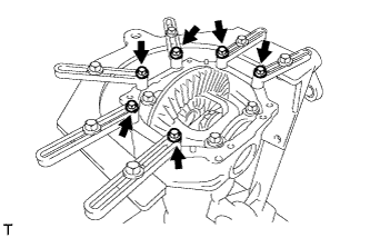
Install the rear differential carrier to the overhaul stand as shown in the illustration.
-
-
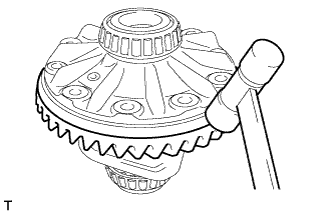
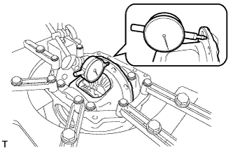
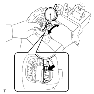
INSPECT RUNOUT OF DIFFERENTIAL RING GEAR
-
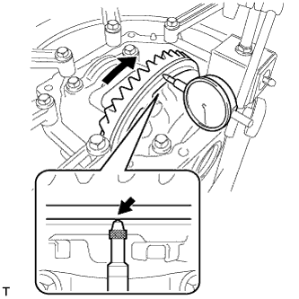
Set a dial indicator perpendicular to the end of the differential ring gear face.
-
Rotate the differential ring gear and measure the runout.
Maximum runout 0.07 mm (0.00275 in.) If the runout is more than the specified maximum value, remove the differential ring gear and check the runout of the rear differential case sub-assembly.
-
-
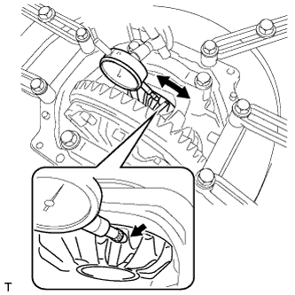
INSPECT DIFFERENTIAL RING GEAR BACKLASH
-
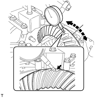
While holding the rear drive pinion companion flange, rotate the differential ring gear and measure the backlash.
Standard Backlash 0.13 to 0.18 mm (0.00512 to 0.00708 in.) Tech Tips
-
Record the measured backlash to use as a reference for selecting a rear differential side gear shaft plate washer.
-
Inspect the tooth contact and use the result as a reference for selecting a rear differential side gear shaft plate washer.
-
-
-
INSPECT TOOTH CONTACT BETWEEN RING GEAR AND DRIVE PINION
-
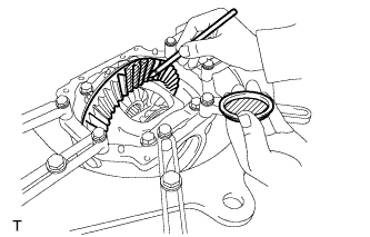
Coat 3 or 4 teeth at 3 different positions on the differential ring gear with Prussian blue.
-
Rotate the differential ring gear in both directions.
-
Inspect the tooth contact pattern.
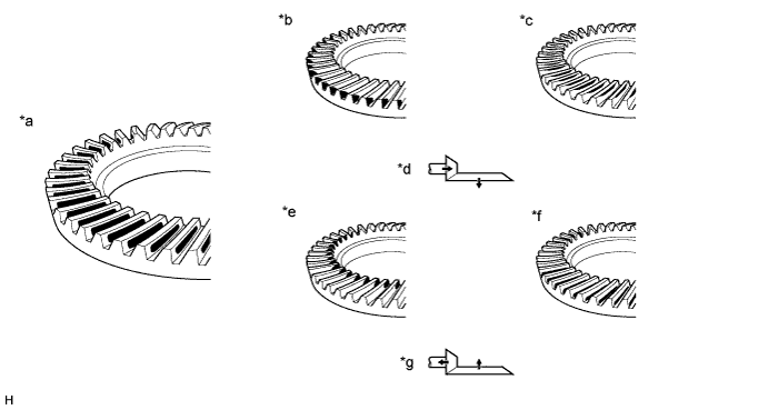
Text in Illustration *a Proper Contact *b Heel Contact *c Face Contact *d Select an adjusting washer that will shift the drive pinion closer to the ring gear (*b, *c) *e Toe Contact *f Flank Contact *g Select an adjusting washer that will shift the drive pinion closer to the ring gear (*e, *f) - -
-
-
INSPECT DIFFERENTIAL SIDE GEAR BACKLASH
-
Place a dial indicator on the tip of a side gear tooth at a right angle. Hold the pinion gear in the rear differential case sub-assembly and check that the backlash is 0 mm (0 in.).
If the result is not as specified, replace the rear differential case sub-assembly with a new one.
-
-
INSPECT RUNOUT OF REAR DRIVE PINION COMPANION FLANGE
-
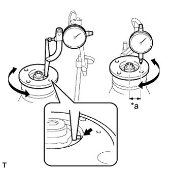
Text in Illustration *a 30 mm (1.18 in.) Using a dial indicator, measure the runout of the rear drive pinion companion flange vertically and horizontally.
Maximum Runout Item Specified Condition Vertical runout 0.09 mm (0.00354 in.) Lateral runout 0.09 mm (0.00354 in.) Note
Measure the runout of the rear drive pinion companion flange horizontally at a position 30 mm (1.18 in.) away from the center of the differential drive pinion shaft.
If the runout is more than the maximum value, replace the rear drive pinion companion flange.
-
-
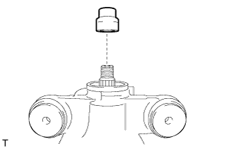
INSPECT DIFFERENTIAL DRIVE PINION PRELOAD
-
Using a torque wrench, measure the starting torque of the differential drive pinion.
Tech Tips
-
The backlash between the differential drive pinion and differential ring gear should allow enough movement of the differential drive pinion to allow this measurement to be performed.
-
Make sure not to include the preload of the differential ring gear (rear differential case sub-assembly) in the measurement of the differential drive pinion preload.
Differential drive pinion preload (at starting) 1.87 to 2.17 N*m (19.07 to 22.13 kgf*cm, 16.55 to 19.21 in.*lbf) -
-
-
INSPECT TOTAL PRELOAD
-
Using a torque wrench, measure the preload with the teeth of the differential drive pinion and differential ring gear in contact.
Total preload (at starting) 2.17 to 2.73 N*m (22.13 to 27.84 kgf*cm, 19.21 to 24.16 in.*lbf)
-
-
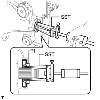
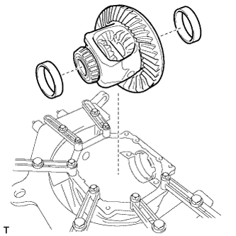
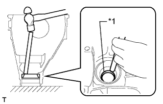
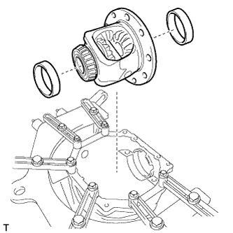
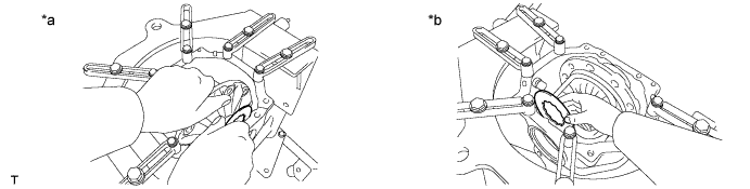
REMOVE REAR DIFFERENTIAL SIDE GEAR SHAFT OIL SEAL
-
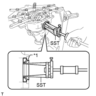
Text in Illustration *1 Rear Differential Side Gear Shaft Oil Seal Using SST, remove the 2 rear differential side gear shaft oil seals.
- SST
- 09308-00010
-
-
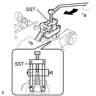
REMOVE REAR DRIVE PINION NUT
-
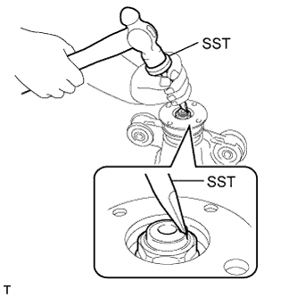
Using SST and a hammer, unstake the staked part of the rear drive pinion nut.
- SST
- 09930-00010
Note
-
Be sure to use SST with the tapered surface facing the differential drive pinion.
-
Do not grind the tip of SST with a grinder, etc.
-
Completely loosen the staked part of the rear drive pinion nut when removing it.
-
Do not damage the threads of the differential drive pinion.
-
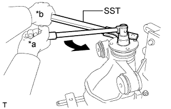
Text in Illustration *a Turn *b Hold Using SST to hold the rear drive pinion companion flange, remove the rear drive pinion nut.
- SST
- 09330-00021
-
-
REMOVE REAR DRIVE PINION COMPANION FLANGE
-
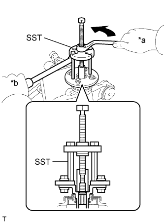
Text in Illustration *a Turn *b Hold Using SST, remove the rear drive pinion companion flange.
- SST
- 09950-30012 ( 09951-03010, 09953-03010, 09954-03010, 09955-03030, 09956-03030 )
Note
Apply grease to the threads of SST center bolt before use.
-
-
REMOVE REAR DIFFERENTIAL DUST DEFLECTOR
Tech Tips
Perform this procedure only when the rear differential dust deflector is damaged.
-
Using SST and a press, remove the rear differential dust deflector.
- SST
- 09950-00020
- 09950-60010 ( 09951-00380 )
- 09950-70010 ( 09951-07100 )
Note
Do not drop the rear drive pinion companion flange.
-
-
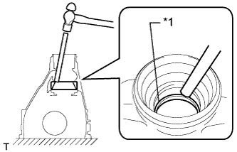
REMOVE REAR DIFFERENTIAL CARRIER OIL SEAL
-
Text in Illustration *1 Rear Differential Carrier Oil Seal Using SST, remove the rear differential carrier oil seal from the rear differential carrier.
- SST
- 09308-00010
-
-
REMOVE REAR DIFFERENTIAL DRIVE PINION OIL SLINGER
-
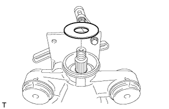
Remove the rear differential drive pinion oil slinger.
-
-
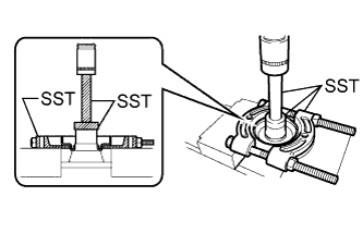
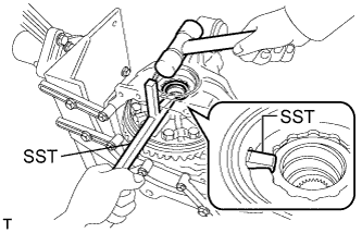
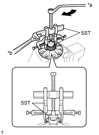
REMOVE REAR DRIVE PINION FRONT TAPERED ROLLER BEARING
-
Text in Illustration *a Turn *b Hold Using SST, remove the rear drive pinion front tapered roller bearing inner race from the differential drive pinion.
- SST
- 09556-22010
Note
Apply grease to the threads and tip of SST center bolt before use.
-
-
REMOVE REAR DIFFERENTIAL DRIVE PINION BEARING SPACER
-
Remove the rear differential drive pinion bearing spacer.
-
-
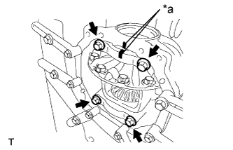
REMOVE REAR DIFFERENTIAL CASE SUB-ASSEMBLY
-
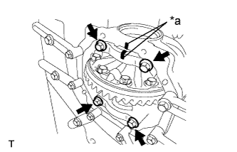
Text in Illustration *a Matchmark Put matchmarks on either bearing cap and the rear differential carrier.
-
Remove the 4 bolts and 2 bearing caps.
Note
Do not exchange bearing caps, as each cap is only suitable for its original location and the installation direction relative to the rear differential carrier for which it was manufactured.
-
Using SST and a hammer, remove the 2 rear differential side gear shaft plate washers.
- SST
- 09504-22011
Note
Put identification marks on the rear differential side gear shaft plate washers to show the location for installation (back side or teeth side), or keep them separate so that they can be distinguished.
Tech Tips
Measure the thickness of each rear differential side gear shaft plate washer and note it.
-
Remove the rear differential case sub-assembly and the rear differential case bearing outer races LH and RH from the rear differential carrier.
Note
-
Do not damage the rear differential case bearing or differential ring gear.
-
Put identification marks on the rear differential case bearing outer races to show the location for installation (back side or teeth side), or keep them separate so that they can be distinguished.
-
-
-
REMOVE REAR DRIVE PINION REAR TAPERED ROLLER BEARING
-
Remove the differential drive pinion from the rear differential carrier.
-
Using SST and a press, remove the rear drive pinion rear tapered roller bearing inner race from the differential drive pinion.
- SST
- 09950-00020
Note
Do not drop the differential drive pinion.
Tech Tips
If either the differential drive pinion or differential ring gear is damaged, replace both as a set.
-
Remove the rear differential drive pinion plate washer from the differential drive pinion.
Tech Tips
Measure the thickness of the rear differential drive pinion plate washer and note it.
-
Text in Illustration *1 Outer Race Using a brass bar and hammer, remove the rear drive pinion rear tapered roller bearing outer race from the rear differential carrier.
Note
Place the brass bar onto the rear drive pinion rear tapered roller bearing outer race. Do not damage the rear differential carrier.
-
-
REMOVE REAR DRIVE PINION FRONT TAPERED ROLLER BEARING
-
Text in Illustration *1 Outer Race Using a brass bar and hammer, remove the rear drive pinion front tapered roller bearing outer race from the rear differential carrier.
Note
Place the brass bar onto the rear drive pinion front tapered roller bearing outer race. Do not damage the rear differential carrier.
-
-
REMOVE DIFFERENTIAL RING GEAR
-
Text in Illustration *a Matchmark Hold the rear differential case sub-assembly in a vise between aluminum plates.
Note
Do not overtighten the vise.
-
Put matchmarks on the differential ring gear and rear differential case sub-assembly.
-
Using a chisel and hammer, unstake the 5 rear differential ring gear set bolt lock plates.
-
Remove the 10 ring gear set bolts and 5 rear differential ring gear set bolt lock plates.
-
Using a plastic-faced hammer, tap on the differential ring gear to separate it from the rear differential case sub-assembly.
Note
Do not damage the differential ring gear.
-
-
INSPECT RUNOUT OF REAR DIFFERENTIAL CASE SUB-ASSEMBLY
Tech Tips
Perform this procedure only when the runout of the differential ring gear exceeds the specified maximum value.
-
Install the rear differential case bearing outer races LH and RH to the rear differential case bearing inner races LH and RH respectively.
Note
-
Be sure to install the rear differential case bearing outer races in the correct position.
-
Do not damage the rear differential case bearing or differential ring gear.
-
-
Install the rear differential case sub-assembly to the rear differential carrier.
-
Install the right and left (back side and teeth side) rear differential side gear shaft plate washers so that there is no looseness in the rear differential case bearings.
Text in Illustration *a Left (Differential Ring Gear Back) Side *b Right (Differential Ring Gear Teeth) Side -
Text in Illustration *a Matchmark Align the matchmarks on the bearing cap and rear differential carrier and install the 2 bearing caps.
Note
Make sure that the right and left bearing caps are not interchanged.
-
Tighten both bearing caps with the 4 bolts.
- Torque:
- 85 N*m { 870 kgf*cm, 63 ft.*lbf }
-
Using a dial indicator, measure the rear differential case sub-assembly runout.
Maximum runout 0.07 mm (0.00275 in.) If the runout is more than the maximum value, replace the rear differential case sub-assembly with a new one.
-
Remove the 4 bolts and 2 bearing caps.
Note
Do not exchange bearing caps, as each cap is only suitable for its original location and the installation direction relative to the carrier for which it was manufactured.
-
Remove the right and left rear differential side gear shaft plate washers.

Text in Illustration *a Left (Differential Ring Gear Back) Side *b Right (Differential Ring Gear Teeth) Side -
Remove the right and left rear differential case bearing outer races and rear differential case sub-assembly.
Note
Do not damage the rear differential case bearing or differential ring gear.
-
-
REMOVE REAR DIFFERENTIAL CASE BEARING
Tech Tips
Perform this procedure only when replacing the rear differential case bearing or rear differential case sub-assembly.
-
Hold the rear differential case sub-assembly in a vise between aluminum plates.
Text in Illustration *a Turn *b Hold Note
Do not overtighten the vise.
-
Using SST, remove the rear differential case bearing inner races LH and RH from the rear differential case sub-assembly.
- SST
- 09950-40011 ( 09951-04020, 09952-04010, 09953-04030, 09954-04010, 09955-04061, 09957-04010, 09958-04011 )
- 09950-60010 ( 09951-00350, 09951-00480, 09952-06010 )
Note
-
Do not deform the bearing cage if the bearing is to be reused.
-
Hook the claws of SST to the rear differential case bearing inner race.
-
Apply grease to the threads and tip of SST center bolt before use.
-
-
INSPECT DIFFERENTIAL SIDE GEAR BACKLASH
-
Secure the rear differential case sub-assembly in a vise between aluminum plates.
Note
Do not overtighten the vise.
-
Place a dial indicator on the tip of a side gear tooth at a right angle. Hold the pinion gear in the rear differential case sub-assembly and check that the backlash is 0 mm (0 in.).
If the result is not as specified, replace the rear differential case sub-assembly with a new one.
-