REAR DIFFERENTIAL CARRIER ASSEMBLY (for 2GR-FSE) REASSEMBLY

-
INSTALL DIFFERENTIAL RING GEAR
-
Clean the contact surfaces of the rear differential case sub-assembly and differential ring gear.
-
Clean the ring gear set bolt hole.
-
Heat the differential ring gear to approximately 100°C (212°F) in boiling water.
-
Carefully take the differential ring gear out of the boiling water.
CAUTION:
Use thick gloves to protect your hands as the differential ring gear is hot.
-
Secure the rear differential case sub-assembly between aluminum plates in a vise.
Note
Do not overtighten the vise.
-
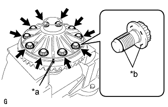
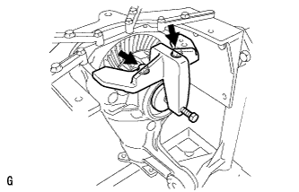
Text in Illustration *a Matchmark *b Thread Lock After the moisture on the differential ring gear has completely evaporated, quickly install the differential ring gear to the rear differential case sub-assembly.
-
Align the matchmarks on the differential ring gear and rear differential case sub-assembly.
-
After the differential ring gear has cooled sufficiently, install 10 new ring gear set bolts to which thread lock has been applied.
Adhesive Toyota Genuine Adhesive 1360K, Three Bond 1360K or equivalent. Note
-
New ring gear set bolts should be used every time the differential ring gear is installed.
-
Do not allow oil to adhere to the ring gear set bolts during installation.
-
-
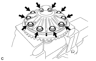
Tighten the 10 ring gear set bolts uniformly, a little at a time.
- Torque:
- 64 N*m { 650 kgf*cm, 47 ft.*lbf }
Note
Tighten diametrically opposite ring gear set bolts in pairs.
-
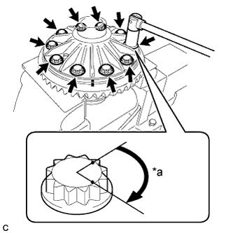
Text in Illustration *a 60° to 90° Tighten the 10 ring gear set bolts an additional 60° to 90°.
Note
Tighten diametrically opposite ring gear set bolts in pairs.
-
-
INSTALL REAR DIFFERENTIAL CASE BEARING
-
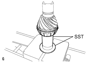
Using SST and a press, install the rear differential case bearing inner races LH and RH to the rear differential case sub-assembly.
- SST
- 09950-60010 ( 09951-00560, 09951-00570 )
- 09950-70010 ( 09951-07100 )

Text in Illustration *a LH Side *b RH Side Note
-
Do not apply hypoid gear oil to a new bearing.
-
Do not deform the bearing cage. Set SST to the center of the rear differential case sub-assembly.
-
If the bearing is replaced, replace it and its outer race as a set.
-
-
INSTALL REAR DRIVE PINION REAR TAPERED ROLLER BEARING
-
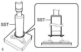
Using SST and a press, install the rear drive pinion rear tapered roller bearing inner race to the differential drive pinion.
- SST
- 09316-60011 ( 09316-00031 )
- 09612-24014 ( 09613-22011 )
-
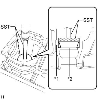
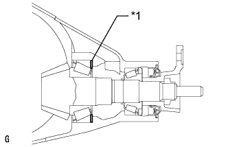
Text in Illustration *1 Rear Drive Pinion Rear Tapered Roller Bearing Outer Race *2 Rear Differential Drive Pinion Plate Washer Using SST and a press, install a new rear differential drive pinion plate washer and rear drive pinion rear tapered roller bearing outer race.
- SST
- 09255-10012
- 09950-70010 ( 09951-07200 )
Tech Tips
Select a rear differential drive pinion plate washer of the same thickness as the removed one.
-
-
INSTALL REAR DRIVE PINION FRONT TAPERED ROLLER BEARING
-
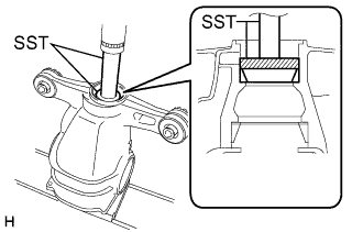
Using SST and a press, install the rear drive pinion front tapered roller bearing outer race.
- SST
- 09950-60020 ( 09951-00710 )
- 09950-70010 ( 09951-07100 )
-
Install the rear drive pinion front tapered roller bearing inner race to the rear differential carrier.
-
-
INSTALL REAR DIFFERENTIAL DUST DEFLECTOR
Tech Tips
Perform this procedure only when replacing the rear differential dust deflector.
-
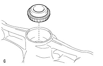
Using SST and a press, insert a new rear differential dust deflector to the rear drive pinion companion flange.
- SST
- 09316-60011 ( 09316-00011 )
Note
-
Slowly press in the rear differential dust deflector. Do not press it excessively.
-
If any burrs remain after pressing in the rear differential dust deflector, remove them.
-
-
INSTALL DIFFERENTIAL DRIVE PINION
-
Using SST and a press, install the differential drive pinion.
- SST
- 09316-60011 ( 09316-00011, 09316-00041 )
- 09608-04031
Tech Tips
Install the rear differential drive pinion bearing spacer and rear differential carrier oil seal after adjusting the tooth contact pattern.
-
-
INSTALL REAR DIFFERENTIAL DRIVE PINION OIL SLINGER
-
Install the rear differential drive pinion oil slinger.
-
-
ADJUST DIFFERENTIAL DRIVE PINION PRELOAD
-
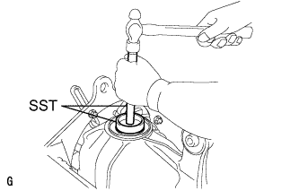
Text in Illustration *a Turn *b Hold Using SST, install the rear drive pinion companion flange.
- SST
- 09950-30012 ( 09951-03010, 09953-03010, 09954-03010, 09955-03040, 09956-03060 )
Note
-
Install the rear drive pinion companion flange so that there is a slight looseness in the differential drive pinion because the rear differential drive pinion bearing spacer is not yet installed.
-
Apply grease to the threads of SST center bolt before use.
-
Coat the threads of the rear drive pinion nut with hypoid gear oil LSD.
-
Text in Illustration *a Turn *b Hold Using SST and a torque wrench, hold the rear drive pinion companion flange and tighten the rear drive pinion nut.
- SST
- 09229-55010
- 09330-00021
- 09950-30012 ( 09955-03040 )
Note
-
Tighten the rear drive pinion nut to approximately 100 N*m (1020 kgf*cm, 74 ft.*lbf), and then tighten it further while checking the preload.
-
Apply hypoid gear oil LSD to the rear drive pinion nut and the threads of the differential drive pinion.
-
As there is no rear differential drive pinion bearing spacer, tighten the rear drive pinion nut a little at a time. Do not overtighten it.
-
Turn the bearing clockwise and counterclockwise several times to stabilize it.
-
Using SST and a torque wrench, measure the preload.
- SST
- 09229-55010
Differential Drive Pinion Preload (at Starting) Item Specified Condition New rear drive pinion tapered roller bearing 1.15 to 1.55 N*m (11.73 to 15.81 kgf*cm, 10.18 to 13.72 in.*lbf) Used rear drive pinion tapered roller bearing 1.15 to 1.55 N*m (11.73 to 15.81 kgf*cm, 10.18 to 13.72 in.*lbf) Note
Record the preload for the total preload measurement.
If the preload is not within the specified range, adjust the rear differential drive pinion preload or perform repairs as necessary.
-
-
INSTALL REAR DIFFERENTIAL CASE SUB-ASSEMBLY
-
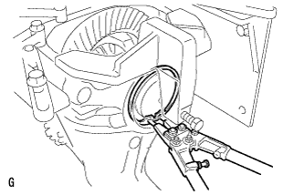
Insert the rear differential case sub-assembly from the differential ring gear tooth side to install the rear differential case sub-assembly as shown in the illustration.
Note
Do not damage the rear differential case bearing or differential ring gear.
-
-
INSTALL REAR DIFFERENTIAL CASE BEARING
-
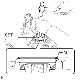
Text in Illustration *a Groove Using SST and a hammer, install the differential side bearing outer race RH to the differential ring gear tooth side.
- SST
- 09608-32010
- 09950-70010 ( 09951-07200 )
Tech Tips
Tap in the rear differential case bearing outer race RH until half of the rear differential side gear shaft snap ring groove of the rear differential carrier can be seen.
-
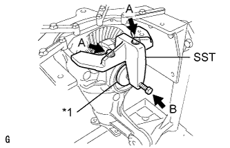
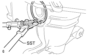
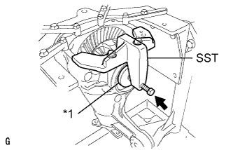
Text in Illustration *1 Disc Install SST to the rear differential carrier with the 2 bolts (A).
- SST
- 09571-50010
-
Tighten SST bolt (B) until SST disc lightly touches the rear differential case bearing outer race RH.
-
Using SST and a hammer, install the rear differential case bearing outer race LH to the differential ring gear back surface side.
- SST
- 09608-32010
- 09950-70010 ( 09951-07200 )
Tech Tips
Tap in the rear differential case bearing outer race LH until it touches the rear differential case bearing inner race roller.
-
-
INSTALL REAR DIFFERENTIAL SIDE GEAR SHAFT SNAP RING
-
Using SST, install the thinnest rear differential side gear shaft snap ring to the back surface of the differential ring gear.
- SST
- 09905-00031
Tech Tips
-
If the final gear set (differential drive pinion and differential ring gear) and rear differential case bearing are new, select a thinner rear differential side gear shaft snap ring and install it.
-
If the final gear set (differential drive pinion and differential ring gear) and rear differential case bearing are reused, install a rear differential side gear shaft snap ring with the same thickness as the removed one.
-
Install a dial indicator to the rear differential carrier.
Tech Tips
Set the dial indicator as shown in the illustration.
-
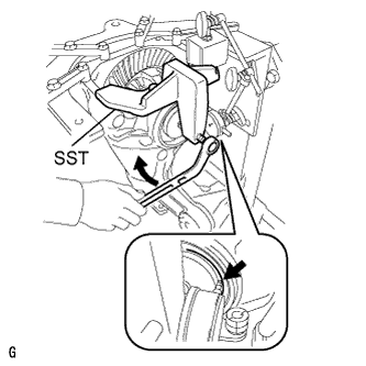
Tighten SST bolt to alter the shape of the rear differential carrier by approximately 0.1 mm (0.00394 in.).
- SST
- 09571-50010
Note
Observe the dial indicator to ensure that the shape of the rear differential carrier does not change by more than 0.2 mm (0.00787 in.).
Tech Tips
Tighten SST bolt to apply the preload to the rear differential case bearing.
-
Turn the differential ring gear clockwise and counterclockwise several times.
-
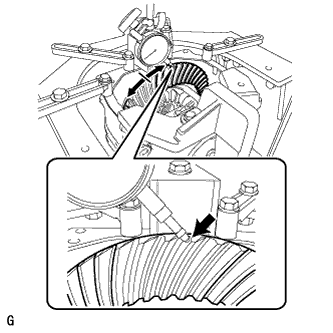
Using a dial indicator, measure the backlash of the differential ring gear at 3 positions.
Backlash 0.08 to 0.13 mm (0.00315 to 0.00511 in.) Note
The difference between the maximum and minimum values must be within 0.05 mm (0.00197 in.).
Tech Tips
-
Record the measured backlash to use as a reference for selecting a rear differential side gear shaft snap ring.
-
If the backlash is not within the specified range, replace the rear differential side gear shaft snap ring on the differential ring gear tooth side with a rear differential side gear shaft snap ring of a different thickness as described in the following procedure.
-
Inspect the tooth contact and use the result as a reference for selecting a rear differential side gear shaft snap ring.
-
-
Loosen SST bolt and separate SST disc from the rear differential case bearing outer race RH.
Note
Do not remove SST.
-
Using SST and a hammer, create a clearance between the rear differential side gear shaft snap ring on the differential ring gear back surface side and the rear differential case bearing outer race LH.
- SST
- 09608-32010
- 09950-70010 ( 09951-07200 )
-
Using SST, remove the rear differential side gear shaft snap ring from the differential ring gear back surface side.
- SST
- 09905-00031
-
Using SST, install a rear differential side gear shaft snap ring with a different thickness.
- SST
- 09905-00031
Tech Tips
When the rear differential side gear shaft snap ring thickness changes by 0.02 mm (0.000787 in.), the backlash also changes by 0.02 mm (0.000787 in.).
Standard Snap Ring Thickness Thickness Thickness 3.66 mm (0.14409 in.) 3.92 mm (0.15433 in.) 4.18 mm (0.16457 in.) 3.68 mm (0.14488 in.) 3.94 mm (0.15512 in.) 4.20 mm (0.16535 in.) 3.70 mm (0.14567 in.) 3.96 mm (0.15591 in.) 4.22 mm (0.16614 in.) 3.72 mm (0.14646 in.) 3.98 mm (0.15669 in.) 4.24 mm (0.16693 in.) 3.74 mm (0.14724 in.) 4.00 mm (0.15748 in.) 4.26 mm (0.16772 in.) 3.76 mm (0.14803 in.) 4.02 mm (0.15827 in.) 4.28 mm (0.16850 in.) 3.78 mm (0.14882 in.) 4.04 mm (0.15905 in.) 4.30 mm (0.16929 in.) 3.80 mm (0.14961 in.) 4.06 mm (0.15984 in.) 4.32 mm (0.17008 in.) 3.82 mm (0.15039 in.) 4.08 mm (0.16063 in.) 4.34 mm (0.17087 in.) 3.84 mm (0.15118 in.) 4.10 mm (0.16142 in.) 4.36 mm (0.17165 in.) 3.86 mm (0.15197 in.) 4.12 mm (0.16220 in.) 4.38 mm (0.17244 in.) 3.88 mm (0.15276 in.) 4.14 mm (0.16299 in.) 4.40 mm (0.17323 in.) 3.90 mm (0.15354 in.) 4.16 mm (0.16378 in.) 4.42 mm (0.17402 in.) -
Using a plastic-faced hammer, lightly tap the differential ring gear tooth side of the rear differential carrier.
-
Install a dial indicator to the rear differential carrier.
Tech Tips
Set the dial indicator as shown in the illustration.
-
Tighten SST bolt to alter the shape of the rear differential carrier by approximately 0.1 mm (0.00394 in.).
- SST
- 09571-50010
Note
Observe the dial indicator to ensure that the shape of the rear differential carrier does not change by more than 0.2 mm (0.00787 in.).
-
Using a dial indicator, measure the backlash of the differential ring gear at 3 positions.
Backlash 0.08 to 0.13 mm (0.00315 to 0.00511 in.) If the backlash is not within the specified range, replace the rear differential side gear shaft snap ring on the back surface of the differential ring gear with one of a different thickness.
Tech Tips
-
Record the measured backlash to use as a reference for selecting a rear differential side gear shaft snap ring.
-
Inspect the tooth contact and use the result as a reference for selecting a rear differential side gear shaft snap ring.
-
-
-
ADJUST REAR DIFFERENTIAL CASE BEARING PRELOAD
-
Install a dial indicator to the rear differential carrier.
Tech Tips
Set the dial indicator as shown in the illustration.
-
Tighten SST bolt to alter the shape of the rear differential carrier by approximately 0.1 mm (0.00394 in.).
- SST
- 09571-50010
Note
Observe the dial indicator to ensure that the shape of the rear differential carrier does not change by more than 0.2 mm (0.00787 in.).
-
Using SST, install the thinnest rear differential side gear shaft snap ring to the differential ring gear tooth side.
- SST
- 09905-00031
-
Text in Illustration *1 Disc Remove the dial indicator and loosen the bolt until SST disc is separated from the rear differential case bearing outer race RH on the differential ring gear tooth side.
-
Using a plastic-faced hammer, lightly tap the differential ring gear tooth side of the rear differential carrier to stabilize the rear differential case bearing.
-
Using a dial indicator, measure the backlash of the differential ring gear at 3 positions. If even one backlash reading is smaller than the specified value, adjust the differential ring gear backlash by replacing the rear differential side gear shaft snap ring on the differential ring gear tooth side with a thicker one.
Backlash 0.08 to 0.13 mm (0.00315 to 0.00511 in.) Tech Tips
If the value is not within the specified range, replace the snap ring with one of a different thickness in the following procedure.
-
Remove the 2 bolts and SST.
-
-
ADJUST TOTAL PRELOAD
-
Using SST and a torque wrench, measure the preload with the teeth of the differential drive pinion and differential ring gear in contact.
- SST
- 09229-55010
Total preload (at starting) for 2WD Item Specified Condition New rear drive pinion tapered roller bearing 1.81 to 3.41 N*m (18.46 to 34.77 kgf*cm, 16.02 to 30.18 in.*lbf) Used rear drive pinion tapered roller bearing 1.64 to 2.86 N*m (16.72 to 29.16 kgf*cm, 14.51 to 25.31 in.*lbf) for AWD Item Specified Condition New rear drive pinion tapered roller bearing 1.66 to 2.99 N*m (16.93 to 30.49 kgf*cm, 14.69 to 26.46 in.*lbf) Used rear drive pinion tapered roller bearing 1.53 to 2.57 N*m (15.60 to 26.21 kgf*cm, 13.54 to 22.75 in.*lbf) Note
-
If the measured preload is less than the specified value, replace the rear differential side gear shaft snap ring of the differential ring gear tooth surface side with a thicker one.
-
If the measured preload is more than the specified value, replace the rear differential side gear shaft snap ring of the differential ring gear tooth surface side with a thinner one.
Tech Tips
When the rear differential side gear shaft snap ring thickness changes by 0.02 mm (0.000787 in.), the total preload will change by approximately 0.1 N*m (1 kgf*cm, 1 in.*lbf).
-
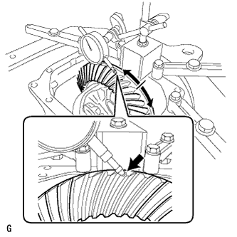
Set a dial indicator to the end of the differential ring gear face.
-
While holding the rear drive pinion companion flange, rotate the differential ring gear and measure the backlash.
Backlash 0.08 to 0.13 mm (0.00315 to 0.00511 in.) Note
-
If the measured value is out of the specified range, adjust it by increasing or decreasing the thickness of both the right and left rear differential side gear shaft snap rings equally.
-
When the rear differential side gear shaft snap ring thickness changes by 0.02 mm (0.000787 in.), the backlash will also change by approximately 0.02 mm (0.000787 in.).
-
-
Recheck the total preload.
-
-
INSPECT TOOTH CONTACT BETWEEN RING GEAR AND DRIVE PINION
-
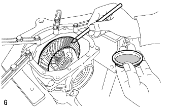
Coat 3 or 4 teeth at 3 different positions on the differential ring gear with Prussian blue.
-
Rotate the differential ring gear in both directions.
-
Inspect the tooth contact pattern.
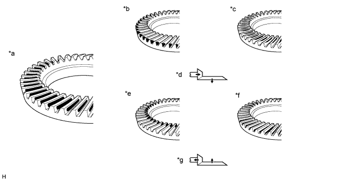
Text in Illustration *a Proper Contact *b Toe Contact *c Face Contact *d Select an adjusting washer that will shift the drive pinion closer to the ring gear (*b, *c) *e Heel Contact *f Flank Contact *g Select an adjusting washer that will shift the drive pinion closer to the ring gear (*e, *f) - - -
Text in Illustration *1 Rear Differential Drive Pinion Plate Washer If the teeth are not contacting properly, use the following table to select a proper rear differential drive pinion plate washer for correction.
Tech Tips
-
If the contact pattern is face contact or flank contact, tooth contact may be adjustable while keeping the backlash within the specified range.
-
If the thickness of the rear differential drive pinion plate washer has been changed, adjust the backlash and measure the total preload.
Standard Plate Washer No. Thickness No. Thickness 88 1.87 to 1.89 mm (0.0736 to 0.0744 in.) 10 2.09 to 2.11 mm (0.0823 to 0.0830 in.) 90 1.89 to 1.91 mm (0.0745 to 0.0751 in.) 12 2.11 to 2.13 mm (0.0831 to 0.0838 in.) 92 1.91 to 1.93 mm (0.0752 to 0.0759 in.) 14 2.13 to 2.15 mm (0.0839 to 0.0846 in.) 94 1.93 to 1.95 mm (0.0760 to 0.0767 in.) 16 2.15 to 2.17 mm (0.0847 to 0.0854 in.) 96 1.95 to 1.97 mm (0.0768 to 0.0775 in.) 18 2.17 to 2.19 mm (0.0855 to 0.0862 in.) 98 1.97 to 1.99 mm (0.0776 to 0.0783 in.) 20 2.19 to 2.21 mm (0.0863 to 0.0870 in.) 00 1.99 to 2.01 mm (0.0784 to 0.0791 in.) 22 2.21 to 2.23 mm (0.0871 to 0.0877 in.) 02 2.01 to 2.03 mm (0.0792 to 0.0799 in.) 24 2.23 to 2.25 mm (0.0878 to 0.0885 in.) 04 2.03 to 2.05 mm (0.0780 to 0.0807 in.) 26 2.25 to 2.27 mm (0.0886 to 0.0893 in.) 06 2.05 to 2.07 mm (0.0808 to 0.0814 in.) 28 2.27 to 2.29 mm (0.0894 to 0.0901 in.) 08 2.07 to 2.09 mm (0.0815 to 0.0822 in.) - - -
-
-
REMOVE REAR DIFFERENTIAL SIDE GEAR SHAFT SNAP RING
-
Text in Illustration *1 Disc Install SST to the rear differential carrier with the 2 bolts (A).
- SST
- 09571-50010
-
Tighten SST bolt (B) until SST disc lightly touches the rear differential case bearing outer race RH on the differential ring gear tooth side.
-
Install a dial indicator to the rear differential carrier.
Tech Tips
Set the dial indicator as shown in the illustration.
-
Tighten SST bolt and alter the shape of the rear differential carrier to create a 0.1 mm (0.00394 in.) clearance between the rear differential case bearing outer race RH and rear differential side gear shaft snap ring.
Note
Observe the dial indicator to ensure that the shape of the rear differential carrier does not change by more than 0.2 mm (0.00787 in.).
Tech Tips
A clearance of approximately 0.1 mm (0.00394 in.) between the rear differential case bearing outer race RH and rear differential side gear shaft snap ring is sufficient for the rear differential side gear shaft snap ring to move slightly.
-
Using SST, remove the rear differential side gear shaft snap ring on the differential ring gear tooth side.
- SST
- 09905-00031
Tech Tips
For reassembly purposes, measure the thickness of the rear differential side gear shaft snap ring. Write down the result.
-
Remove the dial indicator and loosen SST bolt.
Note
Do not remove SST.
-
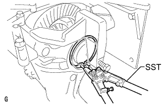
Using SST and a hammer, create a clearance between the rear differential case bearing outer race LH on the back surface of the differential ring gear and the rear differential side gear shaft snap ring.
- SST
- 09608-32010
- 09950-70010 ( 09951-07200 )
Tech Tips
The clearance is not visible, but tapping SST with a hammer 3 or 4 times should be enough.
-
Using snap ring pliers, remove the rear differential side gear shaft snap ring on the back surface of the differential ring gear.
- SST
- 09905-00031
Tech Tips
For reassembly purposes, measure the thickness of the rear differential side gear shaft snap ring. Write down the result.
-
-
REMOVE REAR DIFFERENTIAL CASE BEARING
Tech Tips
Perform this procedure only when replacing the rear differential case bearing or rear differential case sub-assembly.
-
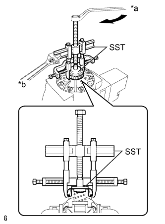
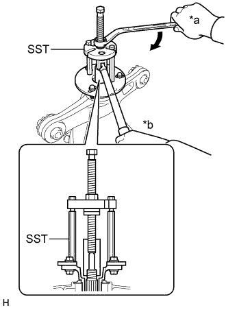
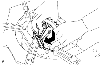
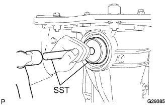
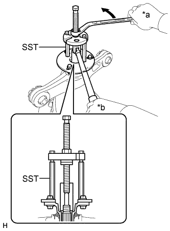
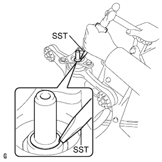
Text in Illustration *a Turn *b Hold Using SST, remove the rear differential case bearing inner races LH and RH from the rear differential case sub-assembly.
- SST
- 09950-40011 ( 09951-04020, 09952-04010, 09953-04030, 09954-04010, 09955-04061, 09957-04010, 09958-04011 )
- 09950-60010 ( 09951-00350, 09951-00480, 09952-06010 )
Note
-
Do not deform the bearing cage if the bearing is to be reused.
-
Hook the claws of SST to the rear differential case bearing inner race.
-
Apply grease to the threads and tip of SST center bolt before use.
-
-
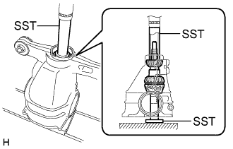
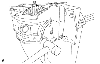
REMOVE REAR DIFFERENTIAL CASE SUB-ASSEMBLY
-
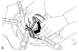
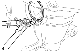
Remove the rear differential case sub-assembly as shown in the illustration.
Note
Do not damage the rear differential case bearing.
-
-
REMOVE REAR DRIVE PINION NUT
-
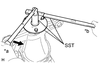
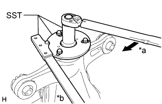
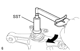
Text in Illustration *a Turn *b Hold Using SST to hold the rear drive pinion companion flange, remove the rear drive pinion nut.
- SST
- 09229-55010
- 09330-00021
- 09950-30012 ( 09955-03040 )
-
-
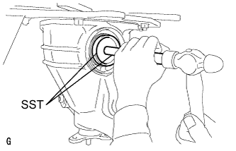
REMOVE REAR DRIVE PINION COMPANION FLANGE
-
Text in Illustration *a Turn *b Hold Using SST, remove the rear drive pinion companion flange.
- SST
- 09950-30012 ( 09951-03010, 09953-03010, 09954-03010, 09955-03040, 09956-03060 )
Note
Apply grease to the threads of SST center bolt before use.
-
-
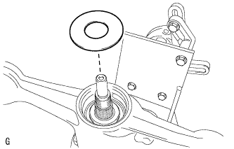
REMOVE REAR DIFFERENTIAL DRIVE PINION OIL SLINGER
-
Remove the rear differential drive pinion oil slinger.
-
-
REMOVE DIFFERENTIAL DRIVE PINION
-
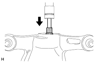
Using a press, remove the differential drive pinion from the rear differential carrier.
Note
Do not drop the differential drive pinion.
-
-
REMOVE REAR DRIVE PINION FRONT TAPERED ROLLER BEARING
-
Remove the rear drive pinion front tapered roller bearing inner race from the rear differential carrier.
-
-
INSTALL REAR DIFFERENTIAL DRIVE PINION BEARING SPACER
-
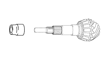
Install a new rear differential drive pinion bearing spacer to the differential drive pinion.
Tech Tips
Install the rear differential drive pinion bearing spacer with the larger diameter side facing toward the differential drive pinion.
-
-
INSTALL REAR DRIVE PINION FRONT TAPERED ROLLER BEARING
-
Install the rear drive pinion front tapered roller bearing inner race to the rear differential carrier.
-
-
INSTALL DIFFERENTIAL DRIVE PINION
-
Using SST and a press, install the differential drive pinion to the rear differential carrier.
- SST
- 09316-60011 ( 09316-00011, 09316-00041 )
- 09608-04031
-
-
INSTALL REAR DIFFERENTIAL DRIVE PINION OIL SLINGER
-
Install the rear differential drive pinion oil slinger.
-
-
INSTALL REAR DIFFERENTIAL CARRIER OIL SEAL
-
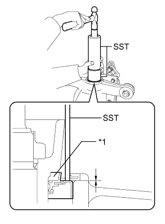
Text in Illustration *1 Rear Differential Carrier Oil Seal Using SST and a hammer, install a new rear differential carrier oil seal.
- SST
- 09316-60011 ( 09316-00011 )
- 09710-30012 ( 09710-04101 )
Standard depth -0.5 to 0.5 mm (-0.0197 to 0.0196 in.) Note
-
Tap the oil seal uniformly so that the oil seal is straight.
-
Do not excessively tap the oil seal.
-
-
INSTALL REAR DRIVE PINION COMPANION FLANGE
-

Text in Illustration *a Turn *b Hold Using SST, install the rear drive pinion companion flange to the differential drive pinion.
- SST
- 09950-30012 ( 09951-03010, 09953-03010, 09954-03010, 09955-03040, 09956-03060 )
Note
Apply grease to the threads of SST center bolt before use.
-
Coat the threads of a new rear drive pinion nut with hypoid gear oil LSD.
-

Text in Illustration *a Turn *b Hold Using SST and a torque wrench, hold the rear drive pinion companion flange and tighten the rear drive pinion nut.
- SST
- 09229-55010
- 09330-00021
- 09950-30012 ( 09955-03040 )
- Torque:
- 490 N*m { 5000 kgf*cm, 361 ft.*lbf, or less }
Note
-
Do not tighten the nut excessively, otherwise the threads will be stripped.
-
Apply hypoid gear oil LSD to the threads of the drive pinion nut and differential drive pinion.
Tech Tips
Tighten the drive pinion nut to approximately 100 N*m (1020 kgf*cm, 74 ft.*lbf), and then tighten it further while observing the preload.
-
-
INSTALL REAR DIFFERENTIAL CASE SUB-ASSEMBLY
-
Insert the rear differential case sub-assembly from the differential ring gear tooth side to install the rear differential case sub-assembly as shown in the illustration.
Note
Do not damage the rear differential case bearing or differential ring gear.
-
-
INSTALL REAR DIFFERENTIAL CASE BEARING
-
Text in Illustration *a Groove Using SST and a hammer, install the rear differential case bearing outer race RH to the differential ring gear tooth side.
- SST
- 09608-32010
- 09950-70010 ( 09951-07200 )
Tech Tips
Tap in the rear differential case bearing outer race until half of the rear differential side gear shaft snap ring groove of the rear differential carrier can be seen.
-
Text in Illustration *1 Disc Install SST to the rear differential carrier with the 2 bolts (A).
- SST
- 09571-50010
-
Tighten SST bolt (B) until SST disc lightly touches the rear differential case bearing outer race RH.
-
Using SST and a hammer, install the rear differential case bearing outer race LH to the differential ring gear back surface side.
- SST
- 09608-32010
- 09950-70010 ( 09951-07200 )
Tech Tips
Tap in the rear differential case bearing outer race until it touches the rear differential case bearing inner race roller.
-
-
INSTALL REAR DIFFERENTIAL SIDE GEAR SHAFT SNAP RING
-
Using SST, install the rear differential side gear shaft snap ring to the rear differential carrier on the differential ring gear back surface side.
- SST
- 09905-00031
Tech Tips
Use the rear differential side gear shaft snap ring installed when performing tooth contact adjustment.
-
Set a dial indicator on the rear differential carrier.
-
Tighten SST bolt to alter the shape of the rear differential carrier by approximately 0.1 mm (0.00394 in.).
Note
Observe the dial indicator to ensure that the shape of the rear differential carrier does not change by more than 0.2 mm (0.00787 in.).
-
Using SST, install the rear differential side gear shaft snap ring to the differential ring gear tooth side.
- SST
- 09905-00031
Tech Tips
Use the rear differential side gear shaft snap ring installed when performing tooth contact adjustment.
-
Remove the dial indicator and tap the rear differential carrier on the differential ring gear tooth side using a plastic-faced hammer to stabilize the rear differential case bearing.
-
Remove the 2 bolts and SST.
-
-
ADJUST DIFFERENTIAL DRIVE PINION PRELOAD
-
Using SST and a torque wrench, measure the starting torque of the differential drive pinion.
- SST
- 09229-55010
Tech Tips
-
The backlash between the differential drive pinion and differential ring gear should allow enough movement of the differential drive pinion to allow this measurement to be performed.
-
Make sure not to include the preload of the differential ring gear (rear differential case sub-assembly) in the measurement of the differential drive pinion preload.
Differential drive pinion preload (at starting) Item Specified Condition New rear drive pinion tapered roller bearing 1.25 to 1.65 N*m (12.75 to 16.83 kgf*cm, 11.06 to 14.60 in.*lbf) Used rear drive pinion tapered roller bearing 1.25 to 1.65 N*m (12.75 to 16.83 kgf*cm, 11.06 to 14.60 in.*lbf)
-
If the preload is less than the specified minimum value, check the preload while retightening the rear drive pinion nut 5 to 10°.
Torque 490 N*m (5000 kgf*cm, 361 ft.*lbf) or less -
If the preload is less than the specified minimum value even when the tightening torque of the rear drive pinion nut is more than the specified maximum value, loosen the rear drive pinion nut and check that the threads of the drive pinion nut and differential drive pinion are not stripped.
-
If the threads are not stripped, replace the rear differential drive pinion bearing spacer. Apply hypoid gear oil LSD to the threads of the differential drive pinion and repeat the procedure.
-
-
INSPECT TOTAL PRELOAD
-
Using SST and a torque wrench, measure the preload with the teeth of the differential drive pinion and differential ring gear in contact.
- SST
- 09229-55010
Total preload (at starting) for 2WD Item Specified Condition New rear drive pinion tapered roller bearing 1.91 to 3.51 N*m (19.48 to 35.79 kgf*cm, 16.90 to 31.07 in.*lbf) Used rear drive pinion tapered roller bearing 1.74 to 2.96 N*m (17.74 to 30.18 kgf*cm, 15.40 to 26.20 in.*lbf) for AWD Item Specified Condition New rear drive pinion tapered roller bearing 1.76 to 3.09 N*m (17.95 to 31.51 kgf*cm, 15.58 to 27.35 in.*lbf) Used rear drive pinion tapered roller bearing 1.63 to 2.67 N*m (16.62 to 27.23 kgf*cm, 14.43 to 23.63 in.*lbf)
-
-
INSPECT DIFFERENTIAL RING GEAR BACKLASH
-
While holding the rear drive pinion companion flange, rotate the differential ring gear and measure the backlash.
Standard Backlash 0.08 to 0.13 mm (0.00315 to 0.00511 in.) If the backlash is not within the specified range, adjust the backlash or perform repairs as necessary.
-
-
INSPECT RUNOUT OF DIFFERENTIAL DRIVE PINION
-
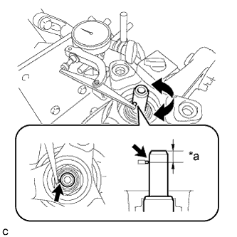
Text in Illustration *a 10 mm (0.394 in.) Using a dial indicator, measure the runout of the differential drive pinion shaft at a position 10 mm (0.394 in.) away from the end of the shaft.
Maximum runout 0.08 mm (0.00315 in.) If the runout is more than the maximum, replace the differential drive pinion and differential ring gear.
-
-
STAKE REAR DRIVE PINION NUT
-
Using SST and a hammer, stake the rear drive pinion nut.
- SST
- 09930-00010
-
-
INSTALL REAR DIFFERENTIAL SIDE GEAR SHAFT OIL SEAL
-
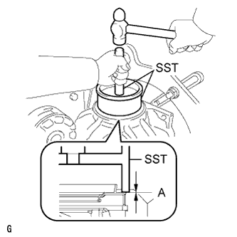
Using SST and a hammer, install 2 new rear differential side gear shaft oil seals.
- SST
- 09223-15030
- 09950-70010 ( 09951-07200 )
Oil seal installation depth (A) -0.5 to 0.5 mm (-0.0197 to 0.0196 in.) Note
-
Make sure to check the identification marks on the rear differential side gear shaft oil seals before installation because the part numbers differ between the left and right sides.
-
To ensure a proper seal, evenly tap in the rear differential side gear shaft oil seals.
-
When installing the rear differential side gear shaft oil seals, tap them in until the outer surface of each seal is flush with the rear differential carrier.
-
Apply MP grease to the rear differential side gear shaft oil seal lips.
-
-
INSTALL REAR DIFFERENTIAL DRAIN PLUG
-
Using a hexagon wrench, install the differential drain plug together with a new gasket.
- Torque:
- 49 N*m { 500 kgf*cm, 36 ft.*lbf }
-
-
REMOVE REAR DIFFERENTIAL CARRIER
-
Remove the 4 bolts and rear differential carrier from the overhaul stand.
Note
Clean the fitting surface between the rear differential carrier and rear differential carrier cover.
-
-
INSTALL REAR DIFFERENTIAL BREATHER PLUG OIL DEFLECTOR
-
Clean the seal packing attached to the rear differential carrier and rear differential carrier cover using a scraper and wire brush. Then remove the oil with non-residue solvent or equivalent.
Note
Do not scratch the sealing surface.
-
Install the rear differential breather plug oil deflector to the rear differential carrier cover with the bolt.
- Torque:
- 7.0 N*m { 70 kgf*cm, 62 in.*lbf }
-
-
INSTALL REAR DIFFERENTIAL CARRIER STRAIGHT PIN
-
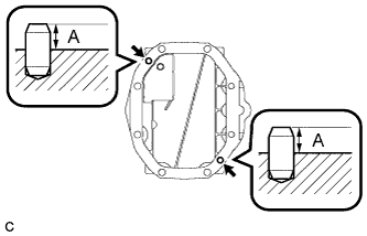
Using a plastic-faced hammer, install the 2 rear differential carrier straight pins to the rear differential carrier cover.
Protrusion (A) 10 to 12 mm (0.394 to 0.472 in.)
-
-
INSTALL REAR DIFFERENTIAL CARRIER COVER
-
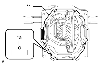
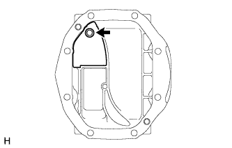
Text in Illustration *1 Seal Packing *a 2 to 3 mm (0.0788 to 0.118 in.) Apply seal packing to the rear differential carrier as shown in the illustration.
Seal packing Toyota Genuine Seal Packing 1281, Three bond 1281 or equivalent Note
-
Apply the seal packing in a continuous line, approximately 2 to 3 mm (0.0787 to 0.118 in.) in diameter.
-
Overlap the seal packing at least 10 mm (0.394 in.) at the beginning and end of application.
-
Install the rear differential carrier cover within 3 minutes of application.
-
-
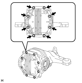
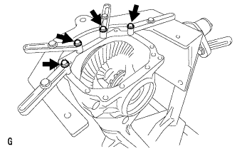
Install the rear differential carrier cover with the 8 bolts.
- Torque:
- 47 N*m { 475 kgf*cm, 34 ft.*lbf }
Note
Do not fill the differential with oil or drive the vehicle immediately after installing the differential carrier cover. Leave the vehicle for at least 1 hour. Also, avoid sudden acceleration and deceleration for at least 12 hours after application.
-
-
INSTALL REAR DIFFERENTIAL BREATHER PLUG
-
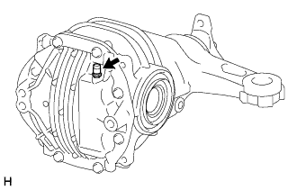
Install the rear differential breather plug to the rear differential carrier cover.
- Torque:
- 21 N*m { 210 kgf*cm, 15 ft.*lbf }
-