REAR DIFFERENTIAL CARRIER OIL SEAL (for 2GR-FSE) REPLACEMENT

-
REMOVE REAR DIFFERENTIAL CARRIER ASSEMBLY
-
REMOVE REAR DIFFERENTIAL CARRIER COVER
-
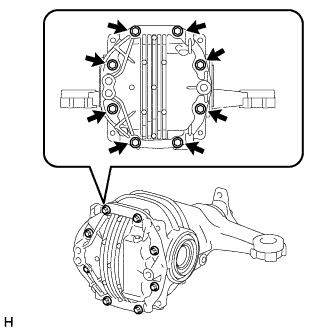
Remove the 8 bolts.
-
Using a brass bar and hammer, remove the rear differential carrier cover from the rear differential carrier.
Note
-
Place the brass bar onto the corners of the rear differential carrier cover.
-
Do not damage the sealing surface of the rear differential carrier.
-
-
-
SECURE REAR DIFFERENTIAL CARRIER ASSEMBLY
-
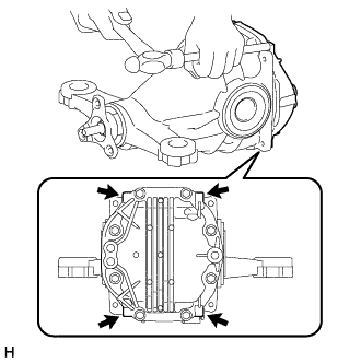
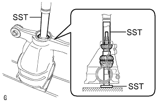
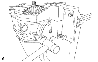
Install the rear differential carrier to an overhaul stand as shown in the illustration.
-
-
REMOVE REAR DIFFERENTIAL SIDE GEAR SHAFT OIL SEAL
-
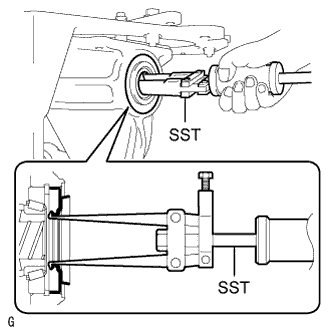
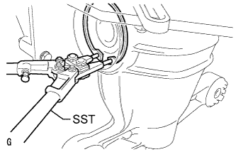
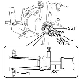
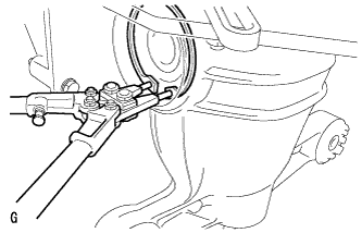
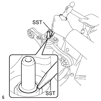
Using SST, remove the 2 rear differential side gear shaft oil seals.
- SST
- 09308-00010
-
-
REMOVE REAR DIFFERENTIAL SIDE GEAR SHAFT SNAP RING
-
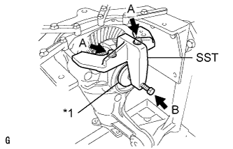
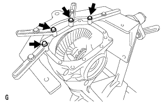
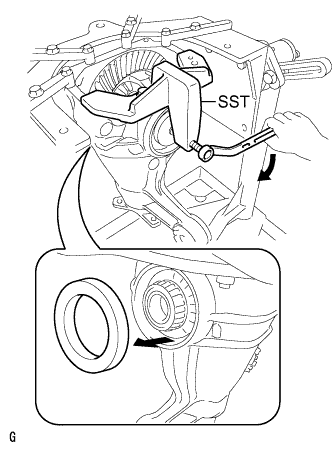
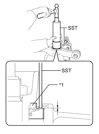
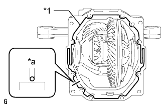
Text in Illustration *1 Disc Install SST to the rear differential carrier with the 2 bolts (A).
- SST
- 09571-50010
-
Tighten SST bolt (B) until SST disc lightly touches the rear differential case bearing outer race RH on the differential ring gear tooth side.
-
Install a dial indicator to the rear differential carrier.
Tech Tips
Set the dial indicator as shown in the illustration.
-
Tighten SST bolt and alter the shape of the rear differential carrier to create a 0.1 mm (0.00394 in.) clearance between the rear differential case bearing outer race RH and rear differential side gear shaft snap ring.
Note
Observe the dial indicator to ensure that the shape of the rear differential carrier does not change by more than 0.2 mm (0.00787 in.).
Tech Tips
A clearance of approximately 0.1 mm (0.00394 in.) between the rear differential case bearing outer race RH and rear differential side gear shaft snap ring is sufficient for the rear differential side gear shaft snap ring to move slightly.
-
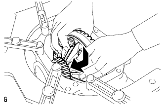
Using SST, remove the rear differential side gear shaft snap ring on the differential ring gear tooth side.
- SST
- 09905-00031
Tech Tips
For reassembly purposes, measure the thickness of the rear differential side gear shaft snap ring. Write down the result.
-
Remove the dial indicator and loosen SST bolt.
Note
Do not remove SST.
-
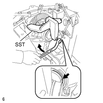
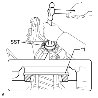
Using SST and a hammer, create a clearance between the rear differential case bearing outer race LH on the back surface of the differential ring gear and the rear differential side gear shaft snap ring.
- SST
- 09608-32010
- 09950-70010 ( 09951-07200 )
Tech Tips
The clearance is not visible, but tapping SST with a hammer 3 or 4 times should be enough.
-
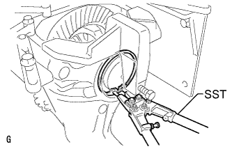
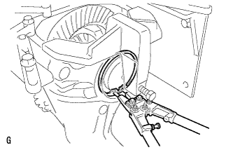
Using snap ring pliers, remove the rear differential side gear shaft snap ring on the back surface of the differential ring gear.
- SST
- 09905-00031
Tech Tips
For reassembly purposes, measure the thickness of the rear differential side gear shaft snap ring. Write down the result.
-
-
REMOVE REAR DIFFERENTIAL CASE BEARING
-
Tighten SST bolt and push out the rear differential case bearing outer race LH on the back surface of the differential ring gear.
- SST
- 09571-50010
Note
Do not drop the rear differential case bearing outer race LH.
Tech Tips
Put identification marks on the rear differential case bearing outer race and rear differential side gear shaft snap ring to show the location for installation (back side or teeth side), or keep the races and snap rings separate so that they can be distinguished.
-
Remove the 2 bolts and SST.
-
Raise the differential ring gear side of the rear differential case sub-assembly slightly to remove the rear differential case bearing outer race RH on the differential ring gear tooth side.
Tech Tips
Put identification marks on the rear differential case bearing outer race and rear differential side gear shaft snap ring to show the location for installation (back side or teeth side), or keep the races and snap rings separate so that they can be distinguished.
-
-
REMOVE REAR DIFFERENTIAL CASE SUB-ASSEMBLY
-
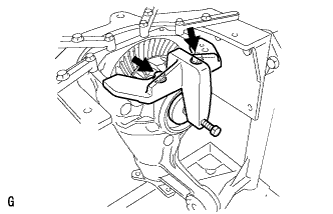
Remove the rear differential case sub-assembly as shown in the illustration.
Note
Do not damage the rear differential case bearing.
-
-
REMOVE REAR DRIVE PINION NUT
-
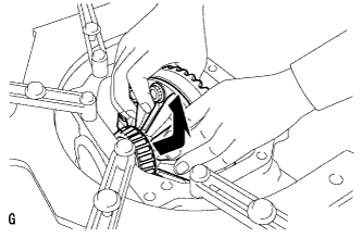
Using SST and a hammer, unstake the staked part of the rear drive pinion nut.
- SST
- 09930-00010
Note
-
Be sure to use SST with the tapered surface facing the differential drive pinion.
-
Do not grind the tip of SST with a grinder, etc.
-
Completely loosen the staked part of the rear drive pinion nut when removing it.
-
Do not damage the threads of the differential drive pinion.
-
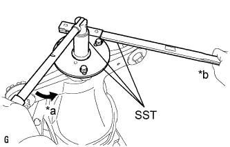
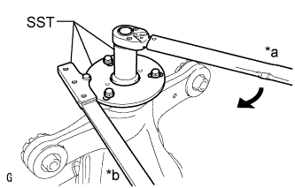
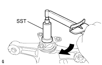
Text in Illustration *a Turn *b Hold Using SST to hold the rear drive pinion companion flange, remove the rear drive pinion nut.
- SST
- 09229-55010
- 09330-00021
- 09950-30012 ( 09955-03040 )
-
-
REMOVE REAR DRIVE PINION COMPANION FLANGE
-
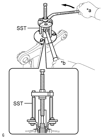
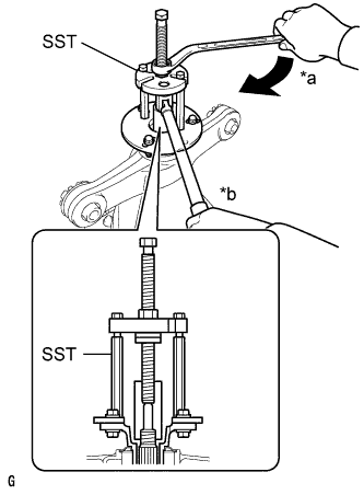
Text in Illustration *a Turn *b Hold Using SST, remove the rear drive pinion companion flange.
- SST
- 09950-30012 ( 09951-03010, 09953-03010, 09954-03010, 09955-03040, 09956-03060 )
Note
Apply grease to the threads of SST center bolt before use.
-
-
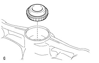
REMOVE REAR DIFFERENTIAL CARRIER OIL SEAL
-
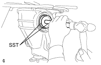
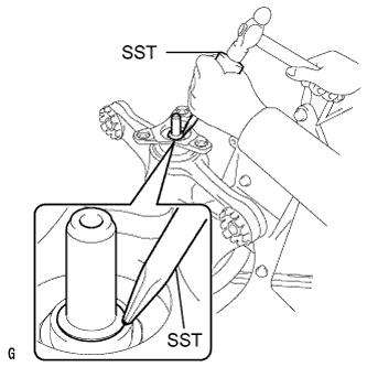
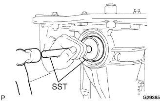
Text in Illustration *1 Rear Differential Carrier Oil Seal Using SST, remove the rear differential carrier oil seal from the rear differential carrier.
- SST
- 09308-00010
-
-
REMOVE REAR DIFFERENTIAL DRIVE PINION OIL SLINGER
-
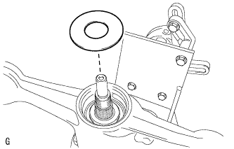
Remove the rear differential drive pinion oil slinger.
-
-
REMOVE REAR DRIVE PINION FRONT TAPERED ROLLER BEARING
-
Remove the rear drive pinion front tapered roller bearing inner race from the rear differential carrier.
-
-
REMOVE DIFFERENTIAL DRIVE PINION
-
Using a press, remove the differential drive pinion from the rear differential carrier.
Note
Do not drop the differential drive pinion.
-
-
REMOVE REAR DIFFERENTIAL DRIVE PINION BEARING SPACER
-
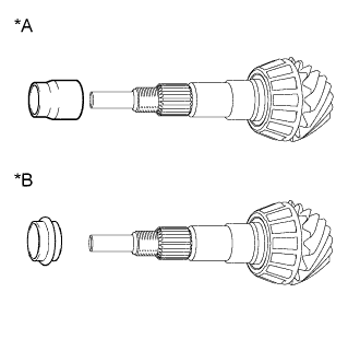
Text in Illustration *A A Type *B B Type Remove the rear differential drive pinion bearing spacer from the differential drive pinion.
-
-
INSTALL REAR DIFFERENTIAL DRIVE PINION BEARING SPACER
-
Text in Illustration *A A Type *B B Type Install a new rear differential drive pinion bearing spacer to the differential drive pinion.
Tech Tips
-
For the A type rear differential drive pinion bearing spacer, install the side with the larger internal diameter towards the differential drive pinion.
-
For the B type rear differential drive pinion bearing spacer, both sides are the same.
-
-
-
INSTALL REAR DRIVE PINION FRONT TAPERED ROLLER BEARING
-
Install the rear drive pinion front tapered roller bearing inner race to the rear differential carrier.
-
-
INSTALL DIFFERENTIAL DRIVE PINION
-
Using SST and a press, install the differential drive pinion to the rear differential carrier.
- SST
- 09316-60011 ( 09316-00011, 09316-00041 )
- 09608-04031
-
-
INSTALL REAR DIFFERENTIAL DRIVE PINION OIL SLINGER
-
Install the rear differential drive pinion oil slinger.
-
-
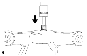
INSTALL REAR DIFFERENTIAL CARRIER OIL SEAL
-
Text in Illustration *1 Rear Differential Carrier Oil Seal Using SST and a hammer, install a new rear differential carrier oil seal.
- SST
- 09316-60011 ( 09316-00011 )
- 09710-30012 ( 09710-04101 )
Standard depth -0.5 to 0.5 mm (-0.0197 to 0.0196 in.) Note
-
Tap the oil seal uniformly so that the oil seal is straight.
-
Do not excessively tap the oil seal.
-
-
INSTALL REAR DRIVE PINION COMPANION FLANGE
-
Text in Illustration *a Turn *b Hold Using SST, install the rear drive pinion companion flange to the differential drive pinion.
- SST
- 09950-30012 ( 09951-03010, 09953-03010, 09954-03010, 09955-03040, 09956-03060 )
Note
Apply grease to the threads of SST center bolt before use.
-
Coat the threads of a new rear drive pinion nut with hypoid gear oil LSD.
-
Text in Illustration *a Turn *b Hold Using SST and a torque wrench, hold the rear drive pinion companion flange and tighten the rear drive pinion nut.
- SST
- 09229-55010
- 09330-00021
- 09950-30012 ( 09955-03040 )
- Torque:
- 490 N*m { 5000 kgf*cm, 361 ft.*lbf, or less }
Note
-
Do not tighten the nut excessively, otherwise the threads will be stripped.
-
Apply hypoid gear oil LSD to the threads of the drive pinion nut and differential drive pinion.
Tech Tips
Tighten the drive pinion nut to approximately 100 N*m (1020 kgf*cm, 74 ft.*lbf), and then tighten it further while observing the preload.
-
-
INSTALL REAR DIFFERENTIAL CASE SUB-ASSEMBLY
-
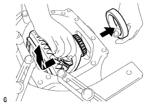
Insert the rear differential case sub-assembly from the differential ring gear tooth side to install the rear differential case sub-assembly as shown in the illustration.
Note
Do not damage the rear differential case bearing or differential ring gear.
-
-
INSTALL REAR DIFFERENTIAL CASE BEARING
-
Using SST and a hammer, install the rear differential case bearing outer race RH to the differential ring gear tooth side.
- SST
- 09608-32010
- 09950-70010 ( 09951-07200 )
Tech Tips
Text in Illustration *1 Groove Tap in the rear differential case bearing outer race until half of the rear differential side gear shaft snap ring groove of the rear differential carrier can be seen.
-
Text in Illustration *1 Disc Install SST to the rear differential carrier with the 2 bolts (A).
- SST
- 09571-50010
-
Tighten SST bolt (B) until SST disc lightly touches the rear differential case bearing outer race RH.
-
Using SST and a hammer, install the rear differential case bearing outer race LH to the differential ring gear back surface side.
- SST
- 09608-32010
- 09950-70010 ( 09951-07200 )
Tech Tips
Tap in the rear differential case bearing outer race until it touches the rear differential case bearing inner race roller.
-
-
INSTALL REAR DIFFERENTIAL SIDE GEAR SHAFT SNAP RING
-
Using SST, install the rear differential side gear shaft snap ring to the rear differential carrier on the differential ring gear back surface side.
- SST
- 09905-00031
Tech Tips
Use the rear differential side gear shaft snap ring installed when performing tooth contact adjustment.
-
Set a dial indicator on the rear differential carrier.
-
Tighten SST bolt to alter the shape of the rear differential carrier by approximately 0.1 mm (0.00394 in.).
Note
Observe the dial indicator to ensure that the shape of the rear differential carrier does not change by more than 0.2 mm (0.00787 in.).
-
Using SST, install the rear differential side gear shaft snap ring to the differential ring gear tooth side.
- SST
- 09905-00031
Tech Tips
Use the rear differential side gear shaft snap ring installed when performing tooth contact adjustment.
-
Remove the dial indicator and tap the rear differential carrier on the differential ring gear tooth side using a plastic-faced hammer to stabilize the rear differential case bearing.
-
Remove the 2 bolts and SST.
-
-
ADJUST DIFFERENTIAL DRIVE PINION PRELOAD
-
Using SST and a torque wrench, measure the starting torque of the differential drive pinion.
- SST
- 09229-55010
Tech Tips
-
The backlash between the differential drive pinion and differential ring gear should allow enough movement of the differential drive pinion to allow this measurement to be performed.
-
Make sure not to include the preload of the differential ring gear (rear differential case sub-assembly) in the measurement of the differential drive pinion preload.
Differential drive pinion preload (at starting) A Type Item Specified Condition New rear drive pinion tapered roller bearing 1.25 to 1.65 N*m (12.75 to 16.83 kgf*cm, 11.06 to 14.60 in.*lbf) Used rear drive pinion tapered roller bearing 1.25 to 1.65 N*m (12.75 to 16.83 kgf*cm, 11.06 to 14.60 in.*lbf) B Type Item Specified Condition New rear drive pinion tapered roller bearing 1.44 to 2.01 N*m (14.68 to 20.50 kgf*cm, 12.74 to 17.79 in.*lbf) Used rear drive pinion tapered roller bearing 0.50 to 0.80 N*m (5.10 to 8.16 kgf*cm, 4.43 to 7.08 in.*lbf)
-
If the preload is less than the specified minimum value, check the preload while retightening the rear drive pinion nut 5 to 10°.
Torque 490 N*m (5000 kgf*cm, 361 ft.*lbf) or less -
If the preload is less than the specified minimum value even when the tightening torque of the rear drive pinion nut is more than the specified maximum value, loosen the rear drive pinion nut and check that the threads of the drive pinion nut and differential drive pinion are not stripped.
-
If the threads are not stripped, replace the rear differential drive pinion bearing spacer. Apply hypoid gear oil LSD to the threads of the differential drive pinion and repeat the procedure.
-
-
INSPECT TOTAL PRELOAD
-
Using SST and a torque wrench, measure the preload with the teeth of the differential drive pinion and differential ring gear in contact.
- SST
- 09229-55010
Total preload (at starting) for 2WD A Type Item Specified Condition New rear drive pinion tapered roller bearing 1.78 to 3.16 N*m (18.15 to 32.22 kgf*cm, 15.75 to 27.97 in.*lbf) Used rear drive pinion tapered roller bearing 1.65 to 2.71 N*m (16.83 to 27.63 kgf*cm, 14.60 to 23.99 in.*lbf) B Type Item Specified Condition New rear drive pinion tapered roller bearing 1.97 to 3.52 N*m (20.09 to 35.89 kgf*cm, 17.44 to 31.15 in.*lbf) Used rear drive pinion tapered roller bearing 0.90 to 1.86 N*m (9.18 to 18.97 kgf*cm, 7.97 to 16.46 in.*lbf) for AWD A Type Item Specified Condition New rear drive pinion tapered roller bearing 1.76 to 3.09 N*m (17.03 to 31.51 kgf*cm, 14.78 to 27.35 in.*lbf) Used rear drive pinion tapered roller bearing 1.63 to 2.67 N*m (16.62 to 27.23 kgf*cm, 14.43 to 23.63 in.*lbf) B Type Item Specified Condition New rear drive pinion tapered roller bearing 1.95 to 3.45 N*m (19.88 to 35.18 kgf*cm, 17.26 to 30.53 in.*lbf) Used rear drive pinion tapered roller bearing 0.88 to 1.82 N*m (8.98 to 18.56 kgf*cm, 7.79 to 16.11 in.*lbf)
-
-
STAKE REAR DRIVE PINION NUT
-
Using SST and a hammer, stake the rear drive pinion nut.
- SST
- 09930-00010
-
-
INSTALL REAR DIFFERENTIAL SIDE GEAR SHAFT OIL SEAL
-
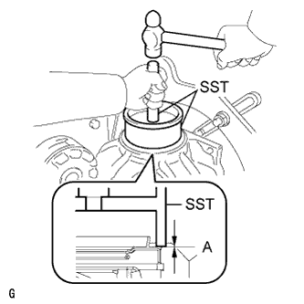
Using SST and a hammer, install 2 new rear differential side gear shaft oil seals.
- SST
- 09223-15030
- 09950-70010 ( 09951-07200 )
Oil seal installation depth (A) -0.5 to 0.5 mm (-0.0197 to 0.0196 in.) Note
-
Make sure to check the identification marks on the rear differential side gear shaft oil seals before installation because the part numbers differ between the left and right sides.
-
To ensure a proper seal, evenly tap in the rear differential side gear shaft oil seals.
-
When installing the rear differential side gear shaft oil seals, tap them in until the outer surface of each seal is flush with the rear differential carrier.
-
Apply MP grease to the rear differential side gear shaft oil seal lips.
-
-
INSTALL REAR DIFFERENTIAL CARRIER COVER
-
Text in Illustration *1 Seal Packing *a 2 to 3 mm (0.0788 to 0.118 in.) Apply seal packing to the rear differential carrier as shown in the illustration.
Seal packing Toyota Genuine Seal Packing 1281, Three bond 1281 or equivalent Note
-
Apply the seal packing in a continuous line, approximately 2 to 3 mm (0.0787 to 0.118 in.) in diameter.
-
Overlap the seal packing at least 10 mm (0.394 in.) at the beginning and end of application.
-
Install the rear differential carrier cover within 3 minutes of application.
-
-
Install the rear differential carrier cover with the 8 bolts.
- Torque:
- 47 N*m { 479 kgf*cm, 35 ft.*lbf }
Note
Do not fill the differential with oil or drive the vehicle immediately after installing the differential carrier cover. Leave the vehicle for at least 1 hour. Also, avoid sudden acceleration and deceleration for at least 12 hours after application.
-
-
INSTALL REAR DIFFERENTIAL CARRIER ASSEMBLY