FRONT DIFFERENTIAL CARRIER ASSEMBLY (for AWD) REASSEMBLY

-
INSTALL DIFFERENTIAL CASE ASSEMBLY
-
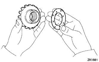
Install the 2 front No. 1 differential thrust washers to the 2 front differential side gears.
Note
-
Make sure that there is no dirt or foreign matter on the front differential thrust washer, front differential side gear, etc. before installing them.
-
If replacing either the front differential side gear or front differential pinion, replace them as a set.
-
Apply hypoid gear oil API GL-5 to all sliding and rotating parts.
-
-
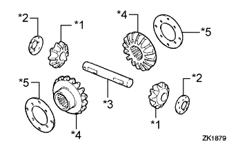
Text in Illustration *1 Front Differential Pinion *2 Front Differential Pinion Thrust Washer *3 Front No. 1 Differential Pinion Shaft *4 Front Differential Side Gear *5 Front No. 1 Differential Side Gear Thrust Washer Install the 2 front differential side gears, 2 front differential pinions, 2 front differential pinion thrust washers and front No. 1 differential pinion shaft to the differential case.
Tech Tips
Align the holes of the differential case and front No. 1 differential pinion shaft.
-
-
ADJUST DIFFERENTIAL PINION AND SIDE GEAR
-
Hold the differential case in a vise between aluminum plates.
Note
Do not overtighten the vise.
-
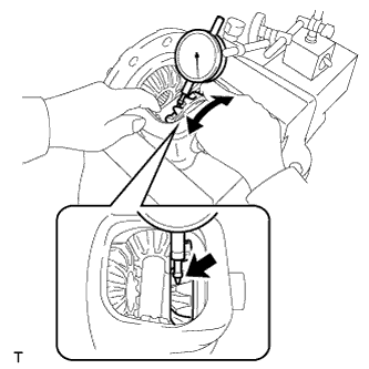
Measure the side gear backlash while holding 1 pinion gear toward the differential case.
Backlash 0.05 to 0.20 mm (0.00197 to 0.00787 in.) If the backlash is not within the specified range, install 2 front No. 1 differential side gear thrust washers of different thicknesses.
Tech Tips
Refer to the following table to select the 2 front No. 1 differential side gear thrust washers.
Washer thickness Mark Thickness mm (in.) 14 0.93 to 0.97 (0.0367 to 0.0381) 02 0.98 to 1.02 (0.0386 to 0.0401) 15 1.03 to 1.07 (0.0406 to 0.0421) 03 1.08 to 1.12 (0.0426 to 0.0440) 16 1.13 to 1.17 (0.0445 to 0.0460) 04 1.18 to 1.22 (0.0465 to 0.0480) -
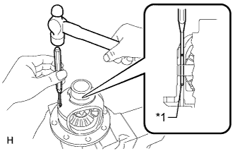
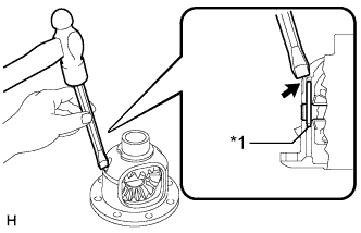
Text in Illustration *1 Front Differential Pinion Shaft Straight Pin Using a 3 mm pin punch and a hammer, install the front differential pinion shaft straight pin through the front differential case and hole of the front No. 1 differential pinion shaft.
-
Text in Illustration *1 Front Differential Pinion Shaft Straight Pin Using a chisel and a hammer, stake the outside of the front differential case pin hole.
-
-
INSTALL DIFFERENTIAL RING GEAR
-
Clean the contact surfaces of the differential case and differential ring gear.
-
Heat the differential ring gear to approximately 100°C (212°F) in boiling water.
CAUTION:
Use thick gloves to protect your hands as the differential ring gear is hot.
-
Carefully take the differential ring gear out of the boiling water.
-
Hold the front differential case in a vise between aluminum plates.
Note
Do not overtighten the vise.
-
After the moisture on the differential ring gear has completely evaporated, quickly install the differential ring gear to the front differential case.
-
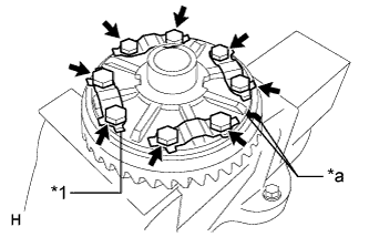
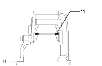
Text in Illustration *1 Lock Plate *a Matchmark Align the matchmarks on the differential ring gear and front differential case.
-
Temporarily install 4 new lock plates and the 8 bolts.
-
After the differential ring gear cools down, tighten the 8 bolts.
- Torque:
- 97 N*m { 985 kgf*cm, 71 ft.*lbf }
-
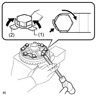
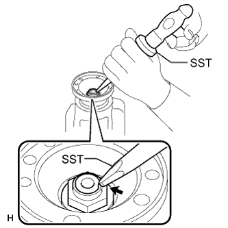
Using a chisel and a hammer, stake the 4 lock plates.
-
Stake one claw so that it is flush against the flat surface of the bolt.
-
Stake the other claw against the surface of the bolt head to act as a stopper if the bolt starts to loosen.
-
-
-
INSTALL FRONT DIFFERENTIAL CASE BEARING
-
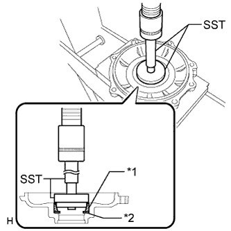
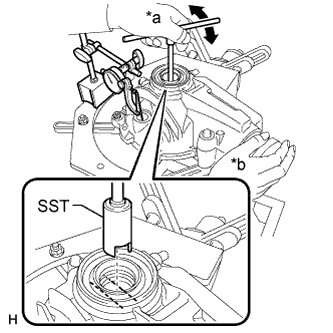
Using SST and a press, install the front differential case bearing inner race LH to the front differential case.
- SST
- 09636-20010
- 09950-60010 ( 09951-00510 )
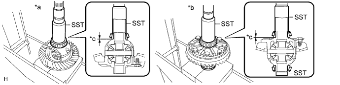
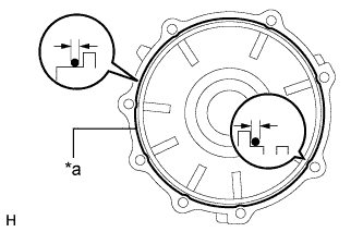
Text in Illustration *a for LH *b for RH *c 0 mm (0 in.) - - Note
-
Do not apply hypoid gear oil to a new bearing.
-
Do not deform the bearing cage.
-
Set SST to the center of the differential case.
-
If the bearing is replaced, replace it and the bearing outer race as a set.
-
Using SST and a press, install the front differential case bearing inner race RH to the front differential case.
Note
-
Do not apply hypoid gear oil to a new bearing.
-
Do not deform the bearing cage.
-
Set SST to the center of the differential case.
-
If the bearing is replaced, replace it and the bearing outer race as a set.
-
-
-
INSTALL FRONT DRIVE PINION REAR TAPERED ROLLER BEARING
-
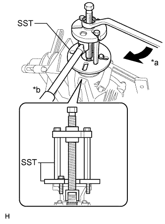
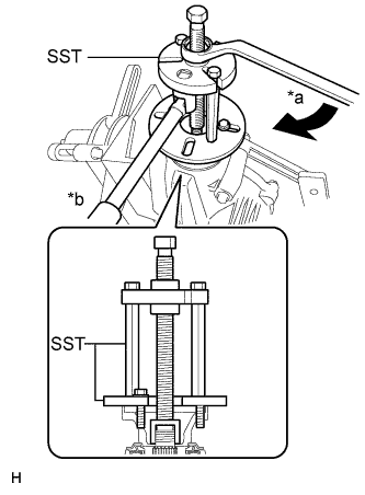
Text in Illustration *1 Outer Race *a Turn *b Hold Using SST, the bolt, nut (M12 X P1.25) and washer, install the outer race of the front drive pinion rear tapered roller bearing.
- SST
- 09950-60020 ( 09951-00710, 09951-00720 )
Note
Do not apply hypoid gear oil to a new bearing.
Tech Tips
-
Bolt: M12 X P1.25, bolt length: 186 mm (09101-12159)
-
Nut: M12 X P1.25 (09101-12159)
-
-
INSTALL FRONT DRIVE PINION FRONT TAPERED ROLLER BEARING
-
Install the front adjust shim to the differential carrier.
-
Text in Illustration *1 Outer Race *2 Adjust Shim *a Turn *b Hold Using SST, the bolt, nut (M12 X P1.25) and washer, install the outer race of the front tapered roller bearing.
- SST
- 09950-60010 ( 09951-00640 )
- 09950-60020 ( 09951-00810 )
Note
Do not apply hypoid gear oil to a new bearing.
Tech Tips
-
Bolt: M12 X P1.25, bolt length: 186 mm (09101-12159)
-
Nut: M12 X P1.25 (90179-12051)
-
Using SST and a press, install the inner race of the front drive pinion front tapered roller bearing to the drive pinion.
- SST
- 09506-30012
Note
Do not apply hypoid gear oil to a new bearing.
-
-
INSTALL FRONT DIFFERENTIAL CASE BEARING
-
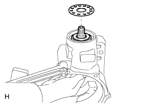
Install the case plate washer to the differential carrier.
-
Text in Illustration *1 Outer Race *2 Case Plate Washer Using SST and a press, install the outer race of the front differential case bearing LH to the differential carrier.
- SST
- 09950-60020
- 09950-70010 ( 09951-00600, 09951-00730, 09951-07100, 09952-06010 )
Note
Do not apply hypoid gear oil to a new bearing.
-
-
INSTALL FRONT DIFFERENTIAL CASE BEARING
-
Install the case plate washer to the differential side bearing retainer.
-
Text in Illustration *1 Outer Race *2 Case Plate Washer Using SST and a press, install the outer race of the front differential case bearing RH to the differential side bearing retainer.
- SST
- 09950-60020
- 09950-70010 ( 09951-00600, 09951-00730, 09951-07100, 09952-06010 )
Note
Do not apply hypoid gear oil to a new bearing.
-
-
INSTALL FRONT DIFFERENTIAL DUST DEFLECTOR
-
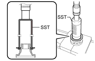
Using SST and a press, install a new front differential dust deflector.
- SST
- 09316-60011 ( 09316-00011 )
Note
-
Slowly press in the dust deflector but not excessively.
-
If any burrs remain after pressing in the deflector, remove them.
-
-
ADJUST DIFFERENTIAL DRIVE PINION PRELOAD
-
Install the drive pinion, inner race of the front drive pinion rear tapered roller bearing and drive pinion oil slinger to the differential carrier.
Tech Tips
Assemble the drive pinion bearing spacer and oil seal after adjusting the gear contact pattern.
-
Text in Illustration *a Turn *b Hold Using SST, install the companion flange.
- SST
- 09950-30012 ( 09951-03010, 09953-03010, 09954-03010, 09955-03030, 09956-03020 )
Note
-
Install the companion flange so that there is a slight looseness in the drive pinion because the bearing spacer is not installed.
-
Apply grease to the threads and tip of SST center bolt before use.
-
Coat the threads of the drive pinion nut with hypoid gear oil LSD.
-
Text in Illustration *a Turn *b Hold Using SST to hold the flange, tighten the drive pinion nut.
- SST
- 09330-00021
- 09950-30012 ( 09955-03030 )
- Torque:
- 263.1 N*m { 2683 kgf*cm, 194 ft.*lbf, or less }
Tech Tips
Tighten the nut approximately 100 N*m (1020 kgf*cm, 74 ft.*lbf), and tighten it further while checking the preload.
Note
-
Apply hypoid gear oil LSD to the nut and the threads of the drive pinion.
-
As there is no bearing spacer, tighten the nut a little at a time and do not overtighten.
-
Turn the bearing clockwise and counterclockwise several times to stabilize it.
-
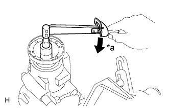
Text in Illustration *a Turn Using a torque wrench, measure the preload.
Drive pinion preload (at starting) Item Specified Condition New bearing 3.6 to 4.3 N*m (37 to 43 kgf*cm, 3 to 3 in.*lbf) Reused bearing 2.7 to 3.3 N*m (28 to 33 kgf*cm, 2 to 2 in.*lbf) Note
-
Record the preload for total preload measurement.
-
Do not apply hypoid gear oil to a new bearing.
If the preload is not within the specified range, adjust the differential drive pinion preload or repair as necessary.
-
-
-
INSTALL FRONT DIFFERENTIAL CASE
-
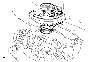
Install the differential case to the differential carrier.
-
-
INSPECT AND ADJUST DIFFERENTIAL RING GEAR AND DIFFERENTIAL DRIVE PINION BACKLASH
-
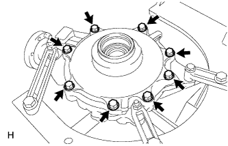
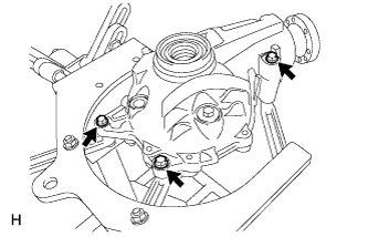
Install the differential side bearing retainer with the 8 bolts.
- Torque:
- 58 N*m { 590 kgf*cm, 43 ft.*lbf }
-
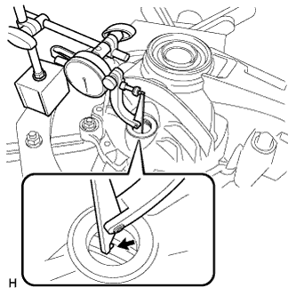
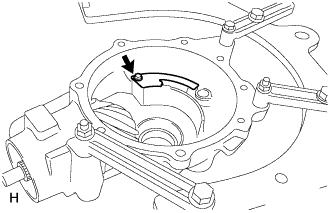
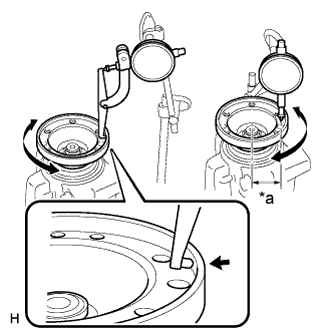
Connect a lever probe to a dial indicator. Insert the probe into the drain plug hole and set it onto the edge of one of the teeth of the ring gear at a right angle.
-

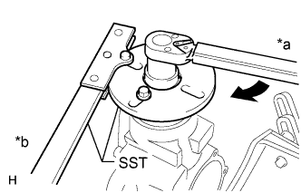
Using SST, turn the differential case clockwise and counterclockwise and measure the ring gear backlash while holding the companion flange with your hand.
- SST
- 09564-32011
Backlash 0.08 to 0.16 mm (0.00315 to 0.00629 in.) Text in Illustration *a Turn *b Hold Tech Tips
-
If a new case bearing is used, select a thinner one and install it.
-
If the case bearing is reused, select a case washer with the same thickness as the removed one.
Washer thickness Thickness mm (in.) Thickness mm (in.) Thickness mm (in.) 2.21 to 2.23 (0.0870 to 0.0877) 2.55 to 2.57 (0.1004 to 0.1011) 2.89 to 2.91 (0.1138 to 0.1145) 2.23 to 2.25 (0.0878 to 0.0885) 2.57 to 2.59 (0.1012 to 0.1019) 2.91 to 2.93 (0.1146 to 0.1153) 2.25 to 2.27 (0.0886 to 0.0893) 2.59 to 2.61 (0.1020 to 0.1027) 2.93 to 2.95 (0.1154 to 0.1161) 2.27 to 2.29 (0.0894 to 0.0901) 2.61 to 2.63 (0.1028 to 0.1035) 2.95 to 2.97 (0.1162 to 0.1169) 2.29 to 2.31 (0.0902 to 0.0909) 2.63 to 2.65 (0.1036 to 0.1043) 2.97 to 2.99 (0.1170 to 0.1177) 2.31 to 2.33 (0.0910 to 0.0917) 2.65 to 2.67 (0.1044 to 0.1051) 2.99 to 3.01 (0.1178 to 0.1185) 2.33 to 2.35 (0.0918 to 0.0925) 2.67 to 2.69 (0.1052 to 0.1059) 3.01 to 3.03 (0.1186 to 0.1192) 2.35 to 2.37 (0.0926 to 0.0933) 2.69 to 2.71 (0.1060 to 0.1066) 3.03 to 3.05 (0.1193 to 0.1200) 2.37 to 2.39 (0.0934 to 0.0940) 2.71 to 2.73 (0.1067 to 0.1074) 3.05 to 3.07 (0.1201 to 0.1208) 2.39 to 2.41 (0.0941 to 0.0948) 2.73 to 2.75 (0.1075 to 0.1082) 3.07 to 3.09 (0.1209 to 0.1216) 2.41 to 2.43 (0.0949 to 0.0956) 2.75 to 2.77 (0.1083 to 0.1090) 3.09 to 3.11 (0.1217 to 0.1224) 2.43 to 2.45 (0.0957 to 0.0964) 2.77 to 2.79 (0.1091 to 0.1098) 3.11 to 3.13 (0.1225 to 0.1232) 2.45 to 2.47 (0.0965 to 0.0972) 2.79 to 2.81 (0.1099 to 0.1106) 3.13 to 3.15 (0.1233 to 0.1240) 2.47 to 2.49 (0.0973 to 0.0980) 2.81 to 2.83 (0.1107 to 0.1114) 3.15 to 3.17 (0.1241 to 0.1248) 2.49 to 2.51 (0.0981 to 0.0988) 2.83 to 2.85 (0.1115 to 0.1122) 3.17 to 3.19 (0.1249 to 0.1255) 2.51 to 2.53 (0.0989 to 0.0996) 2.85 to 2.87 (0.1123 to 0.1129) 3.19 to 3.21 (0.1256 to 0.1263) 2.53 to 2.55 (0.0997 to 0.1003) 2.87 to 2.89 (0.1130 to 0.1137) 3.21 to 3.23 (0.1264 to 0.1271) -
If backlash is not within the specified range, change the thickness of the right and left case washers by equal amounts to adjust it.
-
-
INSPECT TOTAL PRELOAD
-
Text in Illustration *a Turn Using a torque wrench, measure the total preload.
Total preload (at starting) Item Specified Condition New bearing 3.89 to 4.85 N*m (40 to 49 kgf*cm, 3 to 3 in.*lbf) Reused bearing 2.99 to 3.85 N*m (31 to 39 kgf*cm, 3 to 2 in.*lbf) Note
-
If the total preload is not within the specified range, replace the case washer on the ring gear teeth side with another one to adjust it.
-
Do not apply hypoid gear oil to a new bearing.
-
-
-
INSPECT TOOTH CONTACT BETWEEN RING GEAR AND DRIVE PINION
-
Remove the 8 bolts and side bearing retainer.
-
Remove the differential case from the differential carrier.
-
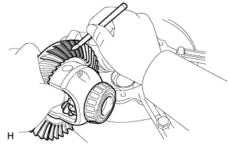
Coat 3 or 4 teeth at 3 different positions on the ring gear with Prussian blue.
-
Install the differential case to the differential carrier.
-
Install the differential side bearing retainer with the 8 bolts.
- Torque:
- 58 N*m { 590 kgf*cm, 43 ft.*lbf }
-
Rotate the ring gear in both directions.
-
Remove the 8 bolts and side bearing retainer.
-
Remove the differential case from the differential carrier.
-
Inspect the tooth contact pattern.
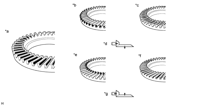
Text in Illustration *a Proper Contact *b Heel Contact *c Face Contact *d Select an adjusting washer that will shift the drive pinion closer to the ring gear (*b, *c) *e Toe Contact *f Flank Contact *g Select an adjusting washer that will shift the drive pinion closer to the ring gear (*e, *f) - - -
Text in Illustration *1 Front Adjust Shim If the teeth are not contacting properly, use the following table to select a proper plate washer for correction.
Note
-
If the contact pattern is either face contact or flank contact, the tooth contact may be adjustable while keeping the backlash within the specified range.
-
If the thickness of the front adjust shim has been changed, adjust the backlash and measure the total preload.
Adjust shim thickness Thickness mm (in.) Thickness mm (in.) 2.35 to 2.37 (0.0925 to 0.0933) 2.53 to 2.55 (0.0997 to 0.1003) 2.37 to 2.39 (0.0934 to 0.0940) 2.55 to 2.57 (0.1004 to 0.1011) 2.39 to 2.41 (0.0941 to 0.0948) 2.57 to 2.59 (0.1012 to 0.1019) 2.41 to 2.43 (0.0949 to 0.0956) 2.59 to 2.61 (0.1020 to 0.1027) 2.43 to 2.45 (0.0937 to 0.0964) 2.61 to 2.63 (0.1028 to 0.1035) 2.45 to 2.47 (0.0965 to 0.0972) 2.63 to 2.65 (0.1036 to 0.1043) 2.47 to 2.49 (0.0973 to 0.0980) 2.65 to 2.67 (0.1044 to 0.1051) 2.49 to 2.51 (0.0981 to 0.0988) 2.67 to 2.69 (0.1052 to 0.1059) 2.51 to 2.53 (0.0989 to 0.0996) 2.69 to 2.71 (0.1060 to 0.1066) -
-
-
REMOVE FRONT DRIVE PINION COMPANION FLANGE FRONT NUT
-
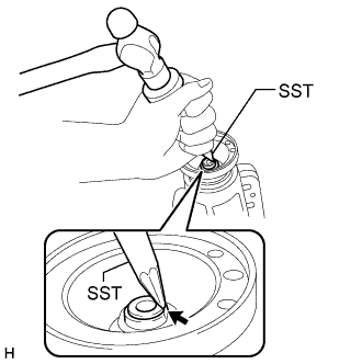
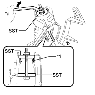
Using SST and a hammer, unstake the staked part of the front drive pinion companion flange front nut.
- SST
- 09930-00010
Note
-
Be sure to use SST with the tapered surface facing the shaft.
-
Do not grind the tip of SST with a grinder, etc.
-
Completely loosen the staked part of the nut when removing it.
-
Do not damage the threads of the drive pinion.
-
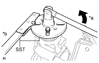
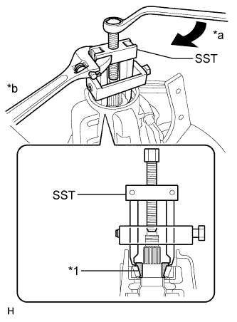
Text in Illustration *a Turn *b Hold Using SST to hold the flange, remove the front drive pinion companion flange front nut.
- SST
- 09330-00021
- 09950-30012 ( 09955-03030 )
Note
Apply grease to the threads and tip of SST center bolt before use.
-
-
REMOVE FRONT DRIVE PINION COMPANION FLANGE SUB-ASSEMBLY FRONT
-
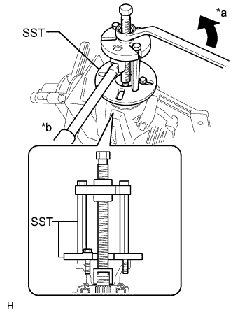
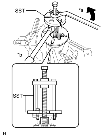
Text in Illustration *a Turn *b Hold Using SST, remove the front drive pinion companion flange sub-assembly front.
- SST
- 09950-30012 ( 09951-03010, 09953-03010, 09954-03010, 09955-03030, 09956-03020 )
Note
Apply grease to the threads and tip of SST center bolt before use.
-
-
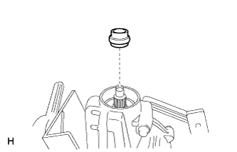
REMOVE FRONT DIFFERENTIAL DRIVE PINION OIL SLINGER
-
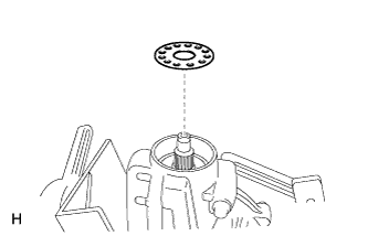
Remove the front differential drive pinion oil slinger.
-
-
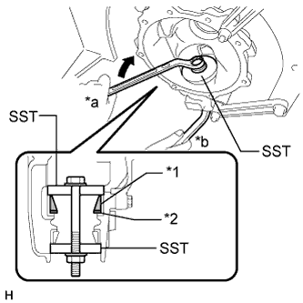
REMOVE FRONT DRIVE PINION REAR TAPERED ROLLER BEARING
-
Text in Illustration *1 Inner Race *a Turn *b Hold Using SST, remove the inner race of the front drive pinion rear tapered roller bearing from the drive pinion.
- SST
- 09556-22010
Note
Apply grease to the threads and tip of SST center bolt before use.
-
-
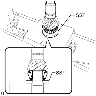
INSTALL FRONT DIFFERENTIAL DRIVE PINION BEARING SPACER
-
Install a new drive pinion bearing spacer to the drive pinion.
Note
Be sure to face the larger inner diameter side rearward as shown in the illustration.
-
-
INSTALL FRONT DRIVE PINION REAR TAPERED ROLLER BEARING
-
Text in Illustration *a Turn *b Hold Using the companion flange, install the inner race of the front drive pinion rear tapered roller bearing to the drive pinion.
- SST
- 09950-30012 ( 09951-03010, 09953-03010, 09954-03010, 09955-03030, 09956-03020 )
Note
Apply grease to the threads and tip of SST center bolt before use.
-
Text in Illustration *a Turn *b Hold Using SST, remove the companion flange.
- SST
- 09950-30012 ( 09951-03010, 09953-03010, 09954-03010, 09955-03030, 09956-03020 )
Note
Apply grease to the threads and tip of SST center bolt before use.
-
-
INSTALL FRONT DIFFERENTIAL DRIVE PINION OIL SLINGER
-
Install the front differential drive pinion oil slinger.
-
-
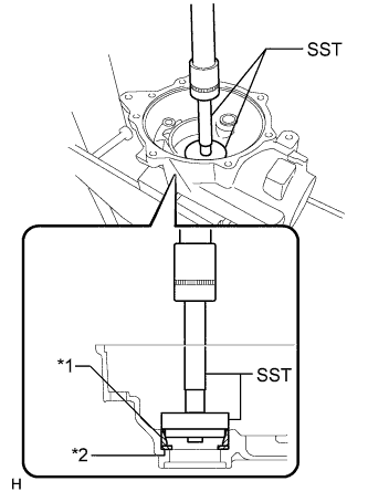
INSTALL FRONT DIFFERENTIAL CARRIER OIL SEAL
-
Text in Illustration *1 Protective Tape *2 Front Differential Carrier Oil Seal Join the 2 SST and secure them with vinyl tape.
- SST
- 09309-36010
- 09502-12010
-
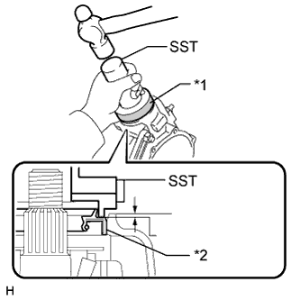
Using SST and a hammer, install a new oil seal.
- SST
- 09309-36010
- 09502-12010
Oil seal drive in depth 0.5 to 1.5 mm (0.0197 to 0.0590 in.)
-
-
INSTALL FRONT DIFFERENTIAL SIDE BEARING RETAINER DEFLECTOR
-
Install the differential side bearing retainer deflector with the bolt.
- Torque:
- 7.0 N*m { 71 kgf*cm, 62 in.*lbf }
-
-
INSTALL FRONT DRIVE PINION COMPANION FLANGE FRONT
-
Text in Illustration *a Turn *b Hold Using SST, install the companion flange to the drive pinion.
- SST
- 09950-30012 ( 09951-03010, 09953-03010, 09954-03010, 09955-03030, 09956-03020 )
Note
Apply grease to the threads and tip of SST center bolt before use.
-
Coat the threads of a new drive pinion nut with hypoid gear oil LSD.
-
Text in Illustration *a Turn *b Hold Using SST to hold the flange, tighten the drive pinion nut.
- SST
- 09330-00021 ( 09955-03030 )
- Torque:
- 263.1 N*m { 2683 kgf*cm, 194 ft.*lbf, or less }
Tech Tips
Tighten the nut approximately 100 N*m (1020 kgf*cm, 74 ft.*lbf), and tighten it further while checking the preload.
-
-
ADJUST DIFFERENTIAL DRIVE PINION PRELOAD
-
Text in Illustration *a Turn Using a torque wrench, measure the preload of the drive pinion.
Preload (at starting) Item Specified Condition New bearing 3.7 to 4.4 N*m (38 to 44 kgf*cm, 3 to 3 in.*lbf) Reused bearing 2.8 to 3.4 N*m (29 to 34 kgf*cm, 3 to 2 in.*lbf)
-
If the preload is less than the specified minimum value, check the preload while retightening the drive pinion nut by 5 to 10° to adjust it into the specified range.
-
If the preload is less than the specified minimum value even when the tightening torque of the drive pinion nut is greater than the specified maximum value, loosen the nut and check that the threads of the drive pinion nut and drive pinion are not stripped.
-
If the threads are not stripped, replace the bearing spacer. Apply hypoid gear oil LSD to the threads of the drive pinion and repeat the procedure.
-
-
-
INSTALL DIFFERENTIAL CASE ASSEMBLY
-
Install the differential case to the differential carrier.
-
-
INSTALL FRONT DIFFERENTIAL SIDE BEARING RETAINER
-
Text in Illustration *a Seal packing Check that there are no foreign objects or damage to the installation surface of the side bearing retainer.
-
Apply FIPG to the side bearing retainer.
FIPG Toyota Genuine Seal Packing 1281, Three Bond 1281 or equivalent Tech Tips
-
Apply FIPG in drops, approximately 1 to 3 mm (0.08 to 0.12 in.) in diameter on the entire surface.
-
Overlap FIPG at least 10 mm (0.39 in.) or more at the beginning and the end of application.
-
Install the carrier cover within 3 minutes after applying FIPG.
-
Do not add oil or drive the vehicle immediately after installing the cover. Leave it for at least an hour. Also, for at least 12 hours, avoid rapid acceleration/deceleration.
-
-
Install the differential side bearing retainer with the 8 bolts.
- Torque:
- 58 N*m { 590 kgf*cm, 43 ft.*lbf }
-
-
INSTALL FRONT DIFFERENTIAL BREATHER PLUG
-
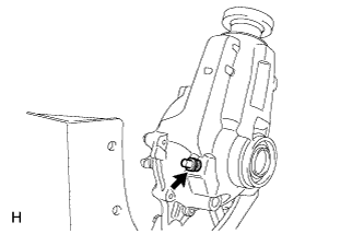
Install the differential breather plug to the differential carrier.
- Torque:
- 21 N*m { 210 kgf*cm, 15 ft.*lbf }
-
-
INSPECT TOTAL PRELOAD
-
Text in Illustration *a Turn Using a torque wrench, measure the total preload.
Total preload (at starting) Item Specified Condition New bearing 3.99 to 4.95 N*m (41 to 50 kgf*cm, 3 to 3 in.*lbf) Reused bearing 3.09 to 3.95 N*m (32 to 40 kgf*cm, 3 to 2 in.*lbf) If the total preload is not within the specified range, adjust the total preload or repair as necessary.
-
-
INSPECT DIFFERENTIAL RING GEAR AND DIFFERENTIAL DRIVE PINION BACKLASH
-
Connect a lever probe to a dial indicator. Insert the probe into the drain plug hole and set it onto the edge of one of the teeth of the ring gear at a right angle.
-
Text in Illustration *a Turn *b Hold Using SST, turn the differential case clockwise and counterclockwise and measure the ring gear backlash while holding the companion flange with your hand.
- SST
- 09564-32011
Backlash 0.08 to 0.16 mm (0.00315 to 0.00629 in.) If the backlash is not within the specified range, adjust the ring gear backlash or repair as necessary.
-
-
INSPECT RUNOUT OF FRONT DRIVE PINION COMPANION FLANGE FRONT
-
Text in Illustration *a 37 mm (1.46 in.) Using a dial indicator, measure the runout of the companion flange vertically and horizontally.
Maximum Runout Item Specified Condition Vertical runout 0.10 mm (0.00394 in.) Lateral runout 0.10 mm (0.00394 in.) If the runout is more than the maximum, replace the companion flange.
-
-
INSTALL FRONT DRIVE PINION COMPANION FLANGE FRONT NUT
-
Using SST and a hammer, stake the drive pinion nut.
- SST
- 09930-00010
-
-
INSTALL FRONT DIFFERENTIAL CASE OIL SEAL
-
INSTALL FRONT DIFFERENTIAL DRAIN PLUG
-
Install the differential drain plug and a new gasket.
- Torque:
- 39 N*m { 400 kgf*cm, 29 ft.*lbf }
-
-
REMOVE FRONT DIFFERENTIAL CARRIER ASSEMBLY
-
Remove the differential carrier from the overhaul stand, etc.
-