STEERING KNUCKLE REMOVAL

-
REMOVE FRONT WHEEL
-
DISCONNECT SPEED SENSOR CONNECTOR (for 2WD)
-
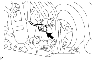
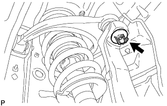
Disconnect the speed sensor connector from the front speed sensor.
Note
-
Be careful not to damage the speed sensor.
-
Prevent foreign matter from adhering to the speed sensor.
-
-
-
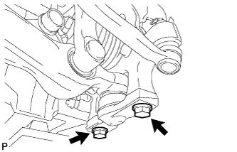
DISCONNECT FRONT SPEED SENSOR (for AWD)
-
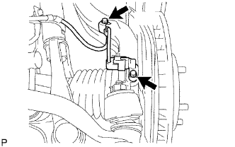
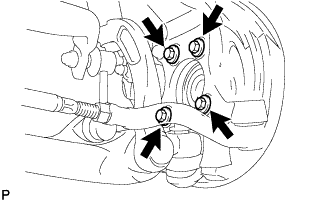
Remove the 2 bolts, and disconnect the speed sensor from the steering knuckle.
Note
-
Be careful not to damage the speed sensor.
-
Prevent foreign matter from adhering to the speed sensor.
-
-
-
DISCONNECT FRONT DISC BRAKE CALIPER ASSEMBLY
-
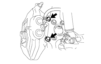
Remove the 2 bolts, and disconnect the brake caliper assembly.
Note
Use a wire or an equivalent to keep the brake caliper from hanging down by the flexible hose.
-
-
REMOVE FRONT DISC (for 17 inch Front Disc Brake)
-
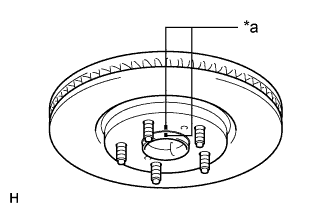
Text in Illustration *a Matchmark Place matchmarks on the front disc and axle hub if planning to reuse the front disc.
-
Remove the front disc.
-
-
REMOVE FRONT DISC (for 18 inch Front Disc Brake)
-
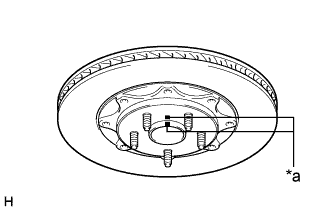
Text in Illustration *a Matchmark Place matchmarks on the front disc and axle hub if planning to reuse the front disc.
-
Remove the front disc.
-
-
REMOVE FRONT AXLE SHAFT NUT (for AWD)
-
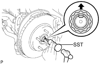
Using SST and a hammer, release the staked part of the front axle shaft nut.
- SST
- 09930-00010
Note
Release the staked part of the nut completely, otherwise the screw of the drive shaft may be damaged.
-
While applying the brakes, remove the front axle shaft nut.
-
-
DISCONNECT FRONT LOWER BALL JOINT ASSEMBLY (for 2WD)
-
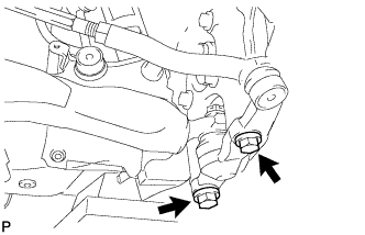
Remove the 2 bolts and steering knuckle from the lower ball joint.
-
-
DISCONNECT FRONT LOWER BALL JOINT ASSEMBLY (for AWD)
-
Remove the 2 bolts, and disconnect the front lower ball joint assembly.
-
-
DISCONNECT TIE ROD ASSEMBLY (for AWD)
-
Remove the clip and castle nut.
-
Install 2 spacers (SST spacer B) to the tie rod assembly LH so that there is a space of approximately 1 mm (0.0397 in.) between the arm and spacers.
- SST
- 09960-20010 ( 09961-02010 )
Note
-
Be sure to install the spacers (SST spacer B) as the steering knuckle spacer may shift.
-
As SST may become damaged, make sure the space between the arm and spacers is not 1 mm (0.0397 in.) or less.
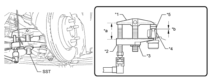
Text in Illustration *1 Body *2 Claw *3 Nut *4 Spacer *5 Spacer B - - *a Parallel *b 1 mm (0.0397 in.) -
Using SST, disconnect the tie rod assembly from the steering knuckle.
- SST
- 09960-20010 ( 09961-02010 )
CAUTION:
Apply MP grease to the threads of SST.
Note
-
Do not damage the dust cover.
-
As the dust cover may be damaged, adjust SST with the center nut so that the body and claw are parallel.
-
Make sure to tie the string of SST to the vehicle to prevent SST from dropping.
-
If the axle carrier spacer (*4) comes out of position, replace the axle carrier.
-
-
REMOVE FRONT AXLE HUB SUB-ASSEMBLY (for 2WD)
-
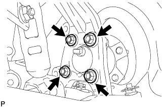
Remove the 4 bolts, front axle hub sub-assembly and front disc brake dust cover.
-
-
REMOVE FRONT AXLE HUB SUB-ASSEMBLY (for AWD)
-
Using a plastic-faced hammer, separate the front drive shaft assembly from the front axle hub.
Note
Be careful not to damage the drive shaft boot.
-
Remove the 4 bolts, front axle hub sub-assembly and front disc brake dust cover.
-
-
REMOVE STEERING KNUCKLE
-
Remove the clip and loosen the nut.
-
Install 2 spacers (SST spacer B) to the front suspension upper arm assembly LH so that there is a space of approximately 1 mm (0.0394 in.) between the arm and spacers.
- SST
- 09960-20010 ( 09961-02060 )
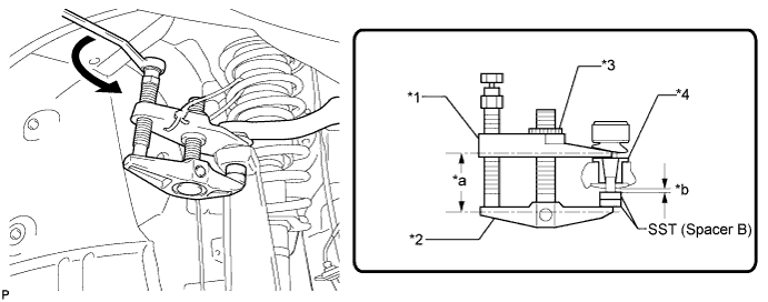
Text in Illustration *1 Claw *2 Body *3 Nut *4 Spacer *a Parallel *b Space of approx. 1 mm Note
-
Be sure to install the spacers (SST spacer B) as the steering knuckle spacer may shift.
-
As SST may become damaged, make sure the space between the arm and spacers is not less than 1 mm (0.0394 in.).
-
Using SST, remove the steering knuckle from the front suspension upper arm assembly LH as shown in the illustration.
- SST
- 09960-20010 ( 09961-02010 )
CAUTION:
Apply MP grease to the threads and end of the SST bolt.
Note
-
Do not damage the dust cover.
-
As the dust cover may be damaged, adjust SST with the center nut so that the body and claw are parallel.
-
Be sure to tie the string of SST to the vehicle to prevent SST from dropping.
-