FRONT AXLE HUB INSTALLATION

-
INSTALL FRONT AXLE HUB SUB-ASSEMBLY (for 2WD)
-
Install the front axle hub sub-assembly with the 4 bolts.
- Torque:
- 69 N*m { 704 kgf*cm, 51 ft.*lbf }
-
-
INSTALL FRONT AXLE HUB SUB-ASSEMBLY (for AWD)
-
Install the front axle hub sub-assembly and front disc brake dust cover with the 4 bolts.
- Torque:
- 69 N*m { 704 kgf*cm, 51 ft.*lbf }
-
Install the front drive shaft assembly to the front axle hub sub-assembly.
Note
Be careful not to damage the front drive shaft boot.
-
-
CONNECT TIE ROD ASSEMBLY (for AWD)
-
Connect the tie rod assembly LH to the steering knuckle with the nut.
- Torque:
- 65 N*m { 663 kgf*cm, 48 ft.*lbf }
-
Install a new clip.
-
-
CONNECT FRONT LOWER BALL JOINT ASSEMBLY (for AWD)
-
Connect the front lower ball joint assembly with the 2 bolts.
- Torque:
- 120 N*m { 1224 kgf*cm, 89 ft.*lbf }
-
-
INSTALL FRONT AXLE SHAFT NUT (for AWD)
-
Clean the threaded parts on the drive shaft and axle shaft nut using a non-residue solvent.
Note
-
Be sure to perform this work for a new drive shaft.
-
Keep the threaded parts free of oil and foreign objects.
-
-
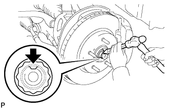
Using the socket wrench (30 mm), install a new front axle shaft nut.
- Torque:
- 294 N*m { 2998 kgf*cm, 217 ft.*lbf }
Tech Tips
Stake the nut after inspecting for looseness and runout in the following steps.
-
-
INSPECT FRONT AXLE HUB BEARING LOOSENESS
-
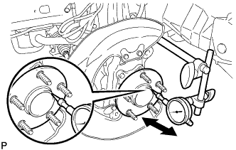
Using a dial indicator, check for looseness near the center of the axle hub.
Maximum 0.05 mm (0.0020 in.) Note
Ensure that the dial indicator is set at right angles to the measurement surface.
If looseness exceeds the maximum, replace the bearing.
-
-
INSPECT FRONT AXLE HUB RUNOUT
-
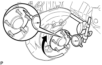
Using a dial indicator, check for runout on the surface of the axle hub outside the hub bolt.
Maximum 0.05 mm (0.0020 in.) Note
Ensure that the dial indicator is set at right angles to the measurement surface.
If runout exceeds the maximum, replace the axle hub.
-
-
INSTALL FRONT DISC (for 17 inch Front Disc Brake)
Note
The front disc has an identification mark. Check the identification mark when installing the disc.
-
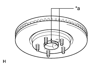
Text in Illustration *a Matchmark Align the matchmarks and install the front disc.
Tech Tips
When replacing the front disc with a new one, select the installation position where the front disc has the smallest runout.
-
-
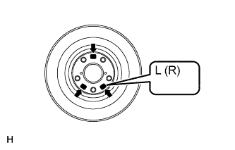
INSTALL FRONT DISC (for 18 inch Front Disc Brake)
Note
-
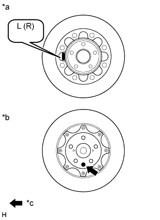
The front disc needs to be installed to the correct side of the vehicle. There is an "L", indicating the disc for the left wheel, or an "R", indicating the disc for the right wheel, engraved on the inside of the disc in the position shown in the illustration.
-
There is pink paint, indicating the disc for the left wheel, or green paint, indicating the disc for the right wheel, on the surface of the front disc in the position shown in the illustration.
Text in Illustration *a Inner Disc *b Outer Disc *c Disc Identification Paint
-
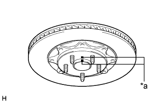
Text in Illustration *a Matchmark Align the matchmarks and install the front disc.
Tech Tips
When replacing the front disc with a new one, select the installation position where the front disc has the smallest runout.
-
-
CONNECT FRONT DISC BRAKE CALIPER ASSEMBLY
-
Connect the front disc brake caliper assembly to the steering knuckle with the 2 bolts.
- Torque:
- 135 N*m { 1377 kgf*cm, 100 ft.*lbf }
Note
-
Do not twist the front brake hose when installing the front disc brake caliper.
-
Make sure that there are no foreign objects or damage to the threads of the bolts.
-
Do not overtighten the bolts because the steering knuckle is made of aluminum and may be damaged.
-
-
INSTALL FRONT AXLE SHAFT NUT (for AWD)
-
Using a chisel and hammer, stake the axle shaft nut.
-
-
CONNECT SPEED SENSOR CONNECTOR (for 2WD)
-
Connect the speed sensor connector to the front speed sensor.
Note
Do not twist the sensor wire.
-
-
CONNECT FRONT SPEED SENSOR (for AWD)
-
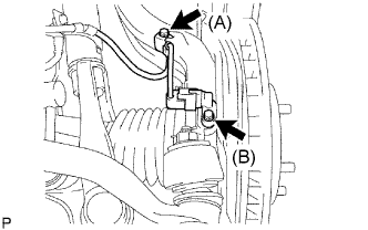
Install the speed sensor to the steering knuckle with the 2 bolts.
- Torque:
- for bolt A
- 6.0 N*m { 61 kgf*cm, 53 in.*lbf }
- for bolt B
- 8.5 N*m { 87 kgf*cm, 75 in.*lbf }
Note
-
Prevent foreign matter from adhering to the speed sensor.
-
Be careful not to damage the speed sensor.
-
Do not twist the sensor wire when installing the speed sensor.
-
-
INSTALL FRONT WHEEL
- Torque:
- 103 N*m { 1050 kgf*cm, 76 ft.*lbf }
-
INSPECT AND ADJUST FRONT WHEEL ALIGNMENT (for AWD)
-
INSPECT SPEED SENSOR SIGNAL