FRONT DRIVE SHAFT ASSEMBLY REASSEMBLY

Note
-
When using a vise, place aluminum plates between the part and vise.
-
When using a vise, do not overtighten it.
-
INSTALL FRONT NO. 1 WHEEL BEARING DUST DEFLECTOR LH
-
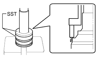
Using SST and a press, install a new front No. 1 wheel bearing dust deflector LH.
- SST
- 09309-36010
- 09387-02010
Note
-
Dust deflector should be completely installed.
-
Be careful not to damage the dust deflector.
-
-
INSTALL FRONT NO. 1 WHEEL BEARING DUST DEFLECTOR RH
Tech Tips
Use the same procedure described for the LH side.
-
INSTALL FRONT DRIVE SHAFT BEARING
-
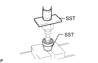
Using SST and a steel plate, install a new front drive shaft bearing.
- SST
- 09527-10011
- 09710-30021 ( 09710-03141 )
Note
Bearing should be completely installed.
-
Using a snap ring expander, install a new front drive shaft hole snap ring RH.
-
-
INSTALL FRONT DRIVE SHAFT DUST COVER LH
-
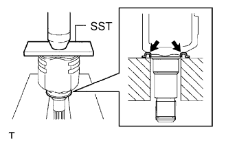
Using SST and a press, install a new drive shaft dust cover LH.
- SST
- 09527-10011
Note
-
Dust cover should be completely installed.
-
Be careful not to damage the dust cover.
-
-
INSTALL FRONT DRIVE SHAFT HOLE SNAP RING LH
-
Install a new front drive shaft hole snap ring LH.
-
-
INSTALL OUTBOARD JOINT BOOT
-
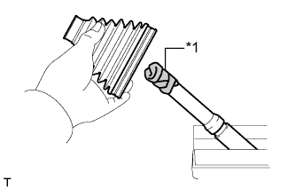
Text in Illustration *1 Protective Tape Before installing the boot, wrap the splines of the drive shaft with protective tape to prevent the boot from being damaged.
-
Install new parts to the front drive outboard joint shaft assembly in the following order.
-
Front No. 2 axle outboard joint boot clamp
-
Outboard joint boot
-
Front axle outboard joint boot clamp
-
-
Pack the front drive outboard joint shaft assembly and outboard joint boot with grease from the boot kit.
Standard Grease Capacity 105 to 125 g (3.7 to 4.4 oz.)
-
-
INSTALL FRONT AXLE OUTBOARD JOINT BOOT CLAMP LH
-
Install the front axle outboard joint boot clamp LH onto the outboard joint boot.
-
Place SST onto the front axle outboard joint boot clamp LH.
- SST
- 09521-24010
-
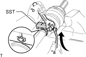
Text in Illustration *a Turn *b Hold Tighten SST so that the front axle outboard joint boot clamp LH is pinched.
Note
Do not overtighten SST.
-
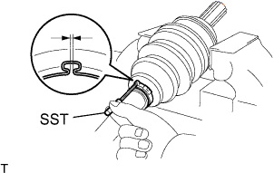
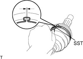
Using SST, measure the clearance of the front axle outboard joint boot clamp LH.
- SST
- 09240-00020 ( 09242-00120, 09242-00300 )
Standard Clearance 1.2 to 4.0 mm (0.0473 to 0.157 in.) Note
If the measured value exceeds the specified value, retighten the boot clamp.
-
-
INSTALL FRONT AXLE OUTBOARD JOINT BOOT CLAMP RH
Tech Tips
Use the same procedure described for the LH side.
-
INSTALL FRONT NO. 2 AXLE OUTBOARD JOINT BOOT CLAMP LH
-
Install the front No. 2 axle outboard joint boot clamp LH onto the outboard joint boot.
-
Place SST onto the front No. 2 axle outboard joint boot clamp LH.
- SST
- 09521-24010
-
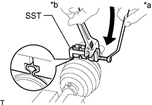
Text in Illustration *a Turn *b Hold Tighten SST so that the front No. 2 axle outboard joint boot clamp LH is pinched.
Note
Do not overtighten SST.
-
Using SST, measure the clearance of the front No. 2 axle outboard joint boot clamp LH.
- SST
- 09240-00020 ( 09242-00120, 09242-00300 )
Standard Clearance 1.2 to 4.0 mm (0.0473 to 0.157 in.) Note
If the measured value exceeds the specified value, retighten the boot clamp.
-
-
INSTALL FRONT NO. 2 AXLE OUTBOARD JOINT BOOT CLAMP RH
Tech Tips
Use the same procedure described for the LH side.
-
INSTALL FRONT DRIVE INBOARD JOINT ASSEMBLY LH
-
Install new parts to the front drive outboard joint shaft assembly LH in the following order.
-
Front axle inboard joint boot clamp LH
-
Inboard joint boot
-
Front No. 2 axle inboard joint boot clamp LH
-
-
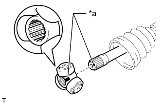
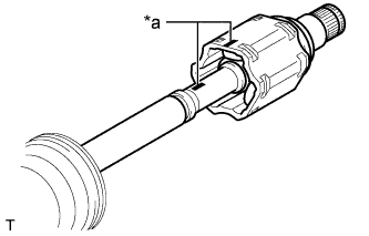
Text in Illustration *a Matchmark Align the matchmarks and place the beveled side of the tripod joint axial spline toward the outboard joint shaft assembly LH.
-
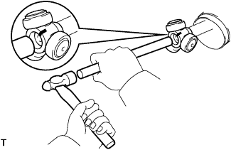
Using a brass bar and hammer, tap in the tripod joint to the outboard joint shaft assembly LH.
Note
-
Do not tap the roller.
-
Be sure to install the tripod joint in the correct direction.
-
-
Using a snap ring expander, install a new front drive inner shaft inner shaft snap ring LH.
-
Pack the front drive inboard joint assembly LH and inboard joint boot with grease from the boot kit.
Standard Grease Capacity 150 to 170 g (5.3 to 5.9 oz.) -
Text in Illustration *a Matchmark Align the matchmarks and install the front drive inboard joint assembly LH to the outboard joint shaft assembly LH.
-
-
INSTALL FRONT DRIVE INBOARD JOINT ASSEMBLY RH
Tech Tips
Use the same procedure described for the LH side.
-
INSTALL INBOARD JOINT BOOT
-
Install the inboard joint boot to the front drive inboard joint assembly.
-
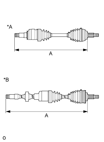
Text in Illustration *A for LH Side *B for RH Side Check that the 2 joint boots are not stretched or contracted when the front drive shaft is at the standard length.
Length (A) Item Length for LH Side 569 mm (1.87 ft.) for RH Side 948.3 mm (3.11 ft.)
-
-
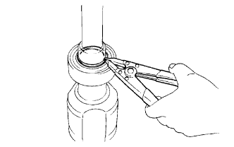
INSTALL FRONT AXLE INBOARD JOINT BOOT CLAMP LH
-
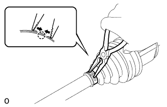
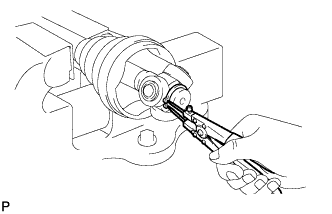
Using needle-nose pliers, install the front axle inboard joint boot clamp LH as shown in the illustration.
-
-
INSTALL FRONT AXLE INBOARD JOINT BOOT CLAMP RH
Tech Tips
Use the same procedure described for the LH side.
-
INSTALL FRONT NO. 2 AXLE INBOARD JOINT BOOT CLAMP LH
Tech Tips
Use the same procedure described for the front axle inboard joint boot clamp LH.
-
INSTALL FRONT NO. 2 AXLE INBOARD JOINT BOOT CLAMP RH
Tech Tips
Use the same procedure described for the LH side.
-
INSPECT FRONT DRIVE SHAFT ASSEMBLY
-
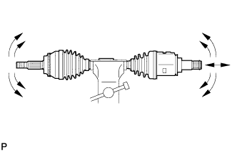
Check that there is no excessive play in the radial direction of the outboard joint.
-
Check that the inboard joint slides smoothly in the thrust direction.
-
Check that there is no severe play in the radial direction of the inboard joint.
-
Check the 2 joint boots for damage.
-
Text in Illustration *A for LH Side *B for RH Side Check that the 2 joint boots are not stretched or contracted when the front drive shaft is at the standard length.
Length (A) Item Length for LH Side 569 mm (1.87 ft.) for RH Side 948.3 mm (3.11 ft.)
-