FOUR WHEEL DRIVE CONTROL SYSTEM AWD Warning Light Remains ON
DESCRIPTION
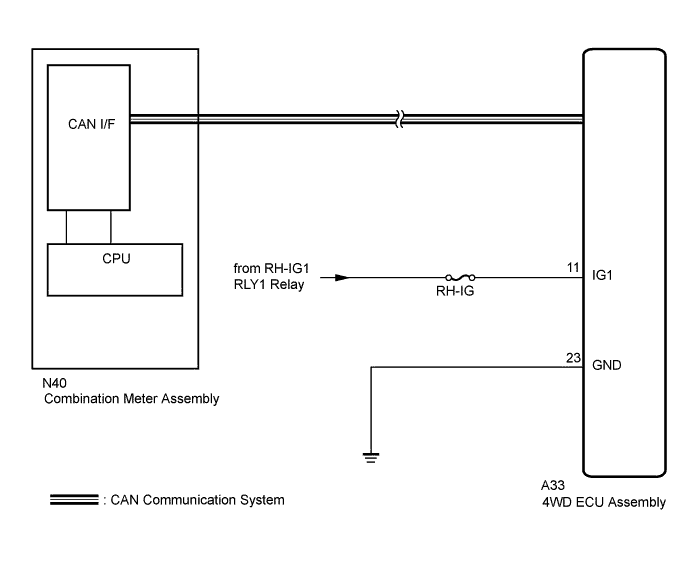
The 4WD ECU assembly is connected to the combination meter assembly via the CAN communication system.
If any of the following is detected, the multi-information display indicates a malfunction in the four-wheel drive control system.
-
There is a malfunction in the 4WD ECU assembly internal circuit.
-
A low voltage is applied to the power source for the 4WD ECU assembly.
-
There is a malfunction in the CAN communication system.
-
There is a malfunction in the brake control system.
-
During fail-safe function.
Tech Tips
When DTC C1297/97, U0100/85, or U0126/84 is detected, the 4WD warning is not displayed.
WIRING DIAGRAM
INSPECTION PROCEDURE
Tech Tips
Check the condition of each related circuit connector before troubleshooting Click here.
PROCEDURE
-
CHECK DTC
-
Check the output DTC Click here.
Result Result Proceed to Neither CAN communication system DTC nor 4WD control system DTC is output A CAN communication DTC is output B 4WD control system DTC is output C Tech Tips
When DTCs indicating a CAN communication system malfunction are output, repair the CAN communication system before repairing each corresponding sensor.
B 
GO TO CAN COMMUNICATION SYSTEM (HOW TO PROCEED WITH TROUBLESHOOTING) Click here
C
REPAIR CIRCUIT INDICATOR BY OUTPUT CODE Click here
A 
-
-
INSPECT BATTERY
-
Check the battery voltage.
Standard voltage 11 to 14 V
NG
INSPECT CHARGING SYSTEM Click here
OK
-
-
CHECK WIRE HARNESS AND CONNECTOR (IG1 TERMINAL)
-
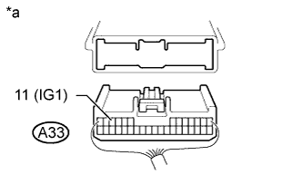
Text in Illustration *a Rear view of wire harness connector
(to 4WD ECU Assembly)
Disconnect the 4WD ECU assembly connector.
-
Turn the engine switch on (IG).
-
Measure the voltage according to the value(s) in the table below.
Standard Voltage Tester Connection Switch Condition Specified Condition A33-11 (IG1) -
Body ground
Engine switch on (IG) 11 to 14 V
NG
REPAIR OR REPLACE HARNESS OR CONNECTOR
OK
-
-
CHECK WIRE HARNESS AND CONNECTOR (GND TERMINAL)
-
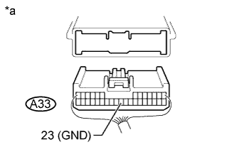
Text in Illustration *a Rear view of wire harness connector
(to 4WD ECU Assembly)
Turn the engine switch off.
-
Disconnect the 4WD ECU assembly connector.
-
Measure the resistance according to the value(s) in the table below.
Standard Resistance Tester Connection Condition Specified Condition A33-23 (GND) -
Body ground
Always Below 1 Ω
NG
REPAIR OR REPLACE HARNESS OR CONNECTOR
OK
-
-
READ VALUE USING GTS (4WD WARNING LIGHT)
-
Turn the engine switch off.
-
Connect the GTS to the DLC3.
-
Turn the engine switch on (IG).
-
Turn the GTS on.
-
Enter the following menus: Chassis / Four Wheel Drive / Active Test Click here.
Four Wheel Drive Tester Display Test Part Control Range Diagnostic Note 4WD Warning Light AWD warning (multi-information display) Warning ON/OFF Observe the multi-information display. -
When performing the 4WD Warning Light Active Test, check 4WD Warning Light in the Data List Click here.
Four Wheel Drive Tester Display Measurement Item/Range Normal Condition Diagnostic Note 4WD Warning Light AWD warning (multi-information display) / ON or OFF ON: Warning on
OFF: Warning off
- Result Result Proceed to Data List Display Data List Display when Performing Active Test ON/OFF Operation ON Changes between ON and OFF A Does not change between ON and OFF B OFF Changes between ON and OFF A Does not change between ON and OFF B
B
REPLACE 4WD ECU ASSEMBLY Click here
A 
GO TO METER / GAUGE SYSTEM (HOW TO PROCEED WITH TROUBLESHOOTING) Click here
-