FOUR WHEEL DRIVE CONTROL SYSTEM TERMINALS OF ECU

Tech Tips
Inspect the connector from the back side while connector is connected.
-
CHECK 4WD ECU ASSEMBLY
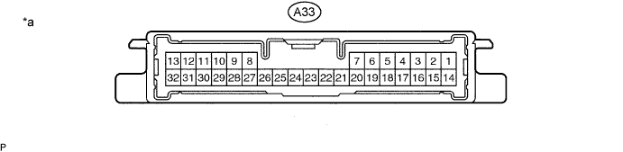
Text in Illustration *a Component with harness connected
(4WD ECU Assembly)
- - Terminal No. (Symbol) Wiring Color Terminal Description Condition Specified Condition A33-11 (IG1) - A33-23 (GND) LG - W-B Power source voltage Engine switch on (IG) 11 to 14 V A33-13 (SLC+) - A33-32 (SLC-) B - R Transfer control solenoid signal D position, idling Pulse generation
(see waveform 1)
A33-14 (CANH) - A33-16 (CANL) V - LG CAN communication line Engine switch off 54 to 69 Ω A33-23 (GND) - Body ground W-B - Body ground Ground Always Below 1 Ω
-
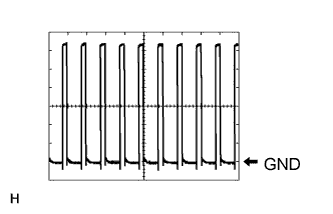
Waveform 1 (Reference):
Item Contents Tool setting 2 V/DIV, 1 ms/DIV Vehicle condition D position, idling
-