TRANSFER ASSEMBLY REASSEMBLY

-
INSTALL TRANSFER CONTROL SOLENOID ASSEMBLY
-
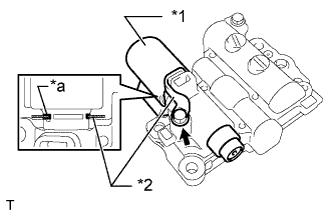
Text in Illustration *1 Transfer Control Solenoid Assembly *2 Solenoid Lock Plate *a Cutout Install the transfer control solenoid assembly and solenoid lock plate to the transfer control valve body assembly with the bolt.
- Torque:
- 6.4 N*m { 65 kgf*cm, 57 in.*lbf }
Tech Tips
Install the solenoid lock plate into the cutout on the transfer control solenoid assembly.
-
-
INSTALL TRANSFER DRIVE SPROCKET BEARING
-
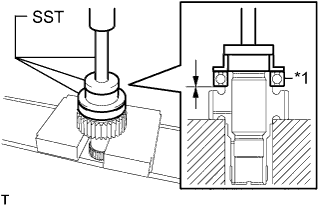
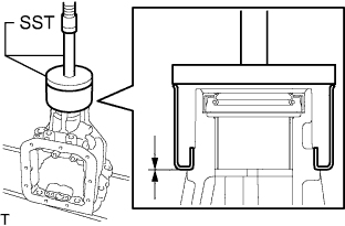
Text in Illustration *1 Transfer Drive Sprocket Bearing Using SST and a press, install a new transfer drive sprocket bearing to the transfer drive sprocket sub-assembly.
- SST
- 09316-20011
- 09950-60010 ( 09951-00640 )
- 09950-70010 ( 09951-07100 )
-
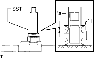
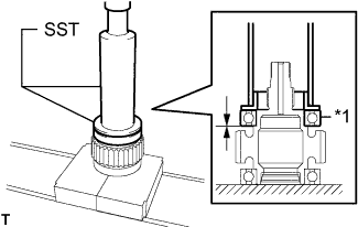
Text in Illustration *1 Transfer Drive Sprocket Bearing *a Shield Facing Upward Using SST and a press, install a new transfer drive sprocket bearing to the transfer drive sprocket sub-assembly.
- SST
- 09316-60011 ( 09316-00011 )
Note
Install the transfer drive sprocket bearing with the shield facing upward.
-
-
INSTALL TRANSFER DRIVEN SPROCKET BEARING
-
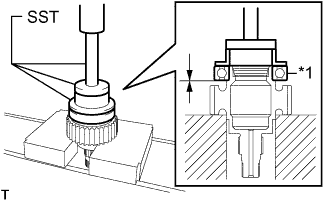
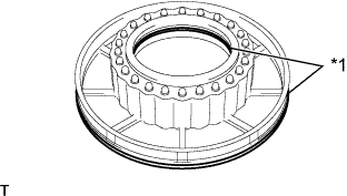
Text in Illustration *1 Transfer Driven Sprocket Bearing Using SST and a press, install a new transfer driven sprocket bearing to the transfer front drive clutch sleeve sub-assembly.
- SST
- 09316-20011
- 09950-60010 ( 09951-00640 )
- 09950-70010 ( 09951-07100 )
-
Text in Illustration *1 Transfer Driven Sprocket Bearing Using SST and a press, install a new transfer driven sprocket bearing to the transfer front drive clutch sleeve sub-assembly.
- SST
- 09316-60011 ( 09316-00011, 09316-00041 )
-
-
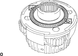
INSTALL TRANSFER CENTER SUPPORT SEAL RING
-
Coat the 2 transfer center support seal rings with ATF.
ATF Toyota Genuine ATF WS -
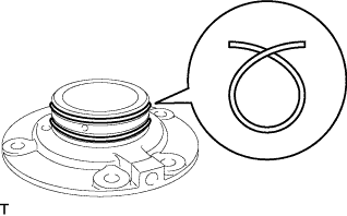
Compress the 2 transfer center support seal rings as shown in the illustration and install them into the grooves on the transfer center support assembly.
Note
-
Do not expand the ring ends excessively.
-
If any ring is damaged or deformed, replace it with a new one.
-
-
-
INSTALL TRANSFER CENTER SUPPORT ASSEMBLY
-
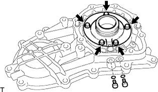
Install the transfer center support assembly to the transfer rear chain case assembly with the 5 bolts.
- Torque:
- 26 N*m { 260 kgf*cm, 19 ft.*lbf }
-
Coat 2 new O-rings with ATF.
ATF Toyota Genuine ATF WS -
Install the 2 O-rings to the screws.
-
Install the 2 screws to the transfer rear chain case assembly.
- Torque:
- 7.4 N*m { 75 kgf*cm, 65 in.*lbf }
-
-
INSTALL TRANSFER DIRECT CLUTCH PISTON O-RING
-
Text in Illustration *1 Transfer Direct Clutch Piston O-ring Coat 2 new transfer direct clutch piston O-rings with ATF.
ATF Toyota Genuine ATF WS -
Install the 2 transfer direct clutch piston O-rings to the center differential clutch piston.
O-ring size: Installation position Inner diameter
mm (in.)
Thickness
mm (in.)
Inner 56.45 to 57.45
(2.223 to 2.261)
2.54 to 2.70
(0.100 to 0.106)
Outer 116.20 to 117.80
(4.575 to 4.637)
3.0 to 3.2
(0.119 to 0.125)
-
-
INSTALL CENTER DIFFERENTIAL CLUTCH PISTON
-
Install the center differential clutch piston to the transfer direct clutch drum sub-assembly.
Note
Do not damage the transfer direct clutch piston O-ring.
-
-
INSTALL TRANSFER DIRECT CLUTCH RETURN SPRING ASSEMBLY
-
Install the transfer direct clutch return spring assembly to the transfer direct clutch drum sub-assembly.
-
-
INSTALL CENTER DIFFERENTIAL CLUTCH PRESSURE BALANCER
-
Text in Illustration *a Rubber Coat the rubber on the center differential clutch pressure balancer with ATF.
ATF Toyota Genuine ATF WS -
Install the center differential clutch pressure balancer to the transfer direct clutch drum sub-assembly.
-
Text in Illustration *1 Transfer Direct Clutch Return Spring Snap Ring Place SST on the center differential clutch pressure balancer, and compress the transfer direct clutch return spring assembly with a press.
- SST
- 09350-30020 ( 09350-07040 )
-
Using SST, install the transfer direct clutch return spring snap ring.
- SST
- 09350-30020 ( 09350-07040, 09350-07070 )
-
-
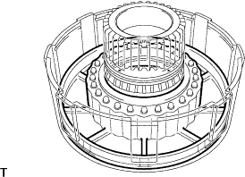
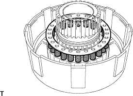
INSTALL CENTER DIFFERENTIAL CLUTCH DISC SET
-
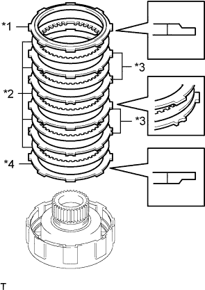
Text in Illustration *1 Center Differential Clutch Disc Flange (No. 1) *2 Center Differential Clutch Disc Set (Discs) *3 Center Differential Clutch Disc Set (Plates) *4 Center Differential Clutch Disc Flange (No. 2) Install the 2 center differential clutch disc flanges and center differential clutch disc set to the transfer direct clutch drum sub-assembly.
Install in the following order *1 - *2 - *3 - *2 - *3 - *2 - *3 - *2 -*3 - *2 - *4 Note
Before assembling new discs, soak them in ATF for at least 15 minutes.
ATF Toyota Genuine ATF WS -
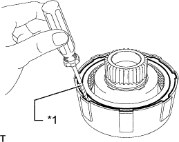
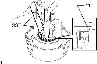
Text in Illustration *1 Protective Tape Using a screwdriver with its tip taped, install the transfer direct clutch flange snap ring to the transfer direct clutch drum sub-assembly.
-
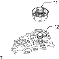
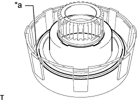
Text in Illustration *1 Transfer Direct Clutch Drum Sub-assembly *2 Transfer Center Support Assembly Install the transfer direct clutch drum sub-assembly to the transfer center support assembly.
-

Text in Illustration *1 Center Differential Clutch Disc Flange (No. 1) *2 Center Differential Clutch Pressure Balancer *3 Center Differential Clutch Piston *a Oil Hole Set the dial indicator perpendicular to the center differential clutch disc flange (No. 1).
-
Apply air (200 kPa, 2.0 kgf/cm2, 19 psi) at the oil hole as shown in the illustration. Measure the pack clearance.
Standard Clearance 0.40 to 0.80 mm (0.0158 to 0.0314 in.) Tech Tips
-
Check that the center differential clutch piston moves smoothly.
-
Perform the measurement at 2 or 3 points and take the average.
-
-
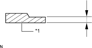
Text in Illustration *1 Center Differential Clutch Disc Flange (No. 1) If the clearance is not within the specified range, select another center differential clutch disc flange (No. 1).
Flange Thickness: Mark Thickness mm (in.) 90 2.95 to 3.05 (0.117 to 0.120) 91 3.15 to 3.25 (0.125 to 0.127) 92 3.35 to 3.45 (0.132 to 0.135) -
Text in Illustration *1 Transfer Direct Clutch Drum Sub-assembly *2 Transfer Center Support Assembly Remove the transfer direct clutch drum sub-assembly from the transfer center support assembly.
-
-
INSTALL TRANSFER REAR OUTPUT SHAFT BEARING
-
Attach the 2 guides to install the transfer rear output shaft bearing to the center differential carrier assembly.
-
-
INSTALL TRANSFER REAR OUTPUT SHAFT ASSEMBLY AND CENTER DIFFERENTIAL CARRIER ASSEMBLY
-
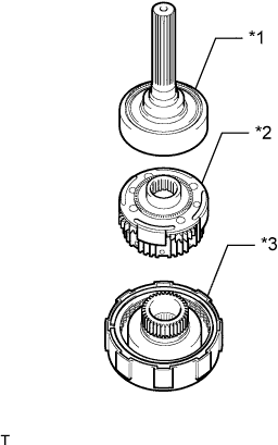
Text in Illustration *1 Transfer Rear Output Shaft Assembly *2 Center Differential Carrier Assembly *3 Transfer Direct Clutch Drum Sub-assembly Install the transfer rear output shaft assembly and center differential carrier assembly to the transfer direct clutch drum sub-assembly.
-
-
INSTALL TRANSFER CHAIN CASE OIL SEAL
-
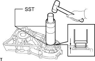
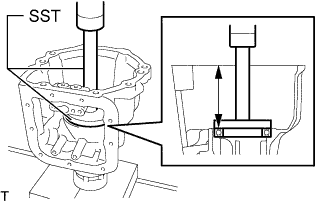
Using SST and a hammer, install a new transfer chain case oil seal.
- SST
- 09316-60011 ( 09316-00011, 09316-00071 )
Oil seal drive in depth 5.6 to 6.2 mm (0.221 to 0.244 in.) -
Apply MP grease to the transfer chain case oil seal lip.
-
-
INSTALL TRANSFER CHAIN CASE GOVERNOR APPLY GASKET
-
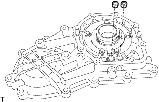
Coat 2 new transfer chain case governor apply gaskets with ATF.
ATF Toyota Genuine ATF WS -
Install the 2 transfer chain case governor apply gaskets to the transfer rear chain case assembly.
-
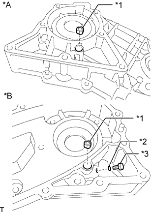
Text in Illustration *A for Front Side *B for Rear Side *1 Transfer Chain Case Governor Apply Gasket *2 O-ring *3 Screw Coat a new O-ring and 2 new transfer chain case governor apply gaskets with ATF.
ATF Toyota Genuine ATF WS -
Install the O-ring to the screw.
-
Install the 2 transfer chain case governor apply gaskets and screw to the transfer front chain case.
- Torque:
- 7.4 N*m { 75 kgf*cm, 65 in.*lbf }
-
-
INSTALL TRANSFER BAFFLE VALVE SUB-ASSEMBLY
-
Install the transfer baffle valve sub-assembly to the transfer rear chain case assembly with the bolt.
- Torque:
- 9.8 N*m { 100 kgf*cm, 87 in.*lbf }
-
-
INSTALL TRANSFER CASE BEARING
-
Using SST and a press, install a new transfer case bearing to the transfer case sub-assembly.
- SST
- 09950-60020 ( 09951-00890 )
- 09950-70010 ( 09951-07150 )
Bearing drive in depth 94.61 to 94.86 mm (3.725 to 3.734 in.)
-
-
INSTALL TRANSFER CASE OIL SEAL
-
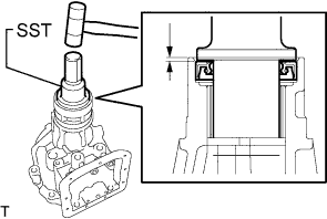
Using SST and a hammer, install a new transfer case oil seal.
- SST
- 09325-40010
Oil Seal Drive in Depth 2.3 to 2.7 mm (0.091 to 0.106 in.) -
Apply MP grease to the transfer case oil seal lip.
-
-
INSTALL TRANSFER EXTENSION HOUSING DUST DEFLECTOR
-
Using SST and a press, install a new transfer extension housing dust deflector to the transfer case sub-assembly.
- SST
- 09950-60020 ( 09951-00910 )
- 09950-70010 ( 09951-07150 )
-
-
INSTALL TRANSFER FRONT CHAIN CASE
-
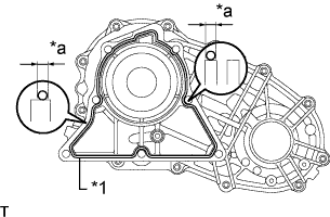
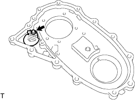
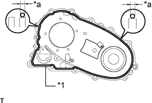
Text in Illustration *1 Seal Packing *a Seal Width 1.0 to 1.5 mm (0.04 to 0.06 in.) Clean the threads of the bolts and the transfer front chain case with non-residue solvent.
-
Apply seal packing to the transfer front chain case as shown in the illustration.
Seal packing Toyota Genuine Seal Packing 1281, Three Bond 1281 or equivalent Note
Reassemble the parts within 5 minutes of applying fresh FIPG material. Otherwise, the packing (FIPG) material must be removed and reapplied.
-
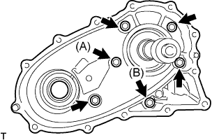
Temporarily install the 6 bolts in several steps, and then tighten them to the specified torque.
- Torque:
- 34 N*m { 345 kgf*cm, 25 ft.*lbf }
Tech Tips
-
Bolt A: 57 mm (2.244 in.)
-
Bolt B: 74 mm (2.913 in.)
-
Other Bolts: 45 mm (1.771 in.)
Bolt length:
-
-
INSTALL TRANSFER FRONT DRIVE CHAIN, TRANSFER DRIVE SPROCKET SUB-ASSEMBLY AND TRANSFER FRONT DRIVE CLUTCH SLEEVE SUB-ASSEMBLY
-
Install the transfer front drive chain to the transfer drive sprocket sub-assembly and transfer front drive clutch sleeve sub-assembly.
-
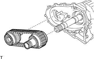
Install the transfer front drive chain, transfer drive sprocket sub-assembly and transfer front drive clutch sleeve sub-assembly.
-
-
INSTALL TRANSFER REAR CHAIN CASE ASSEMBLY
-
Text in Illustration *1 Seal Packing *a Seal Width 1.0 to 1.5 mm (0.04 to 0.06 in.) Clean the threads of the bolts and the transfer rear chain case assembly with non-residue solvent.
-
Apply seal packing to the transfer rear chain case assembly as shown in the illustration.
Seal packing Toyota Genuine Seal Packing 1281, Three Bond 1281 or equivalent Note
Reassemble the parts within 5 minutes of applying fresh FIPG material. Otherwise, the packing (FIPG) material must be removed and reapplied.
-
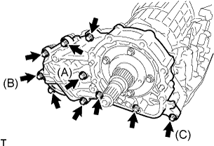
Temporarily install the 10 bolts in several steps, and then tighten them to the specified torque.
- Torque:
- Bolt A
- 57 N*m { 579 kgf*cm, 42 ft.*lbf }
- Bolt B, Bolt C and Other Bolts
- 34 N*m { 345 kgf*cm, 25 ft.*lbf }
Tech Tips
-
Bolt A: 60 mm (2.362 in.)
-
Bolt B: 50 mm (1.969 in.)
-
Bolt C: 109 mm (4.291 in.)
-
Other Bolts: 40 mm (1.574 in.)
Bolt length:
-
-
INSTALL FLANGE YOKE ASSEMBLY
-
Install the flange yoke assembly.
-
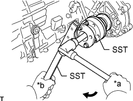
Text in Illustration *a Turn *b Hold Using SST, hold the flange yoke assembly.
- SST
- 09213-54015 ( 91651-60855 )
- 09330-00021
-
Using a 30 mm deep socket wrench, install a new flange yoke nut.
- Torque:
- 123 N*m { 1249 kgf*cm, 90 ft.*lbf }
-
Using a chisel and hammer, stake the flange yoke nut.
-
-
INSTALL TRANSFER REAR OUTPUT SHAFT ASSEMBLY
-
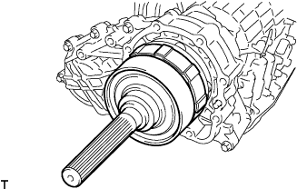
Install the transfer rear output shaft assembly.
-
-
INSTALL TRANSFER CASE SUB-ASSEMBLY
-
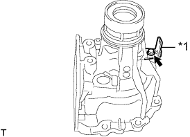
Text in Illustration *1 Clamp Install the clamp to the transfer case sub-assembly with the bolt.
- Torque:
- 5.4 N*m { 55 kgf*cm, 48 in.*lbf }
-
Text in Illustration *1 Seal Packing *a Seal Width 1.0 to 1.5 mm (0.04 to 0.06 in.) Clean the threads of the bolts and the transfer case sub-assembly with non-residue solvent.
-
Apply seal packing to the transfer case sub-assembly as shown in the illustration.
Seal packing Toyota Genuine Seal Packing 1281, Three Bond 1281 or equivalent Note
Reassemble the parts within 5 minutes of applying fresh FIPG material. Otherwise, the packing (FIPG) material must be removed and reapplied.
-
Text in Illustration *1 Clamp Temporarily install the 8 bolts and clamp in several steps, and then tighten them to the specified torque.
- Torque:
- 34 N*m { 345 kgf*cm, 25 ft.*lbf }
Tech Tips
-
Bolt A: 88 mm (3.465 in.)
-
Bolt B: 40 mm (1.574 in.)
Bolt length:
-
-
INSTALL TRANSFER CONTROL VALVE BODY ASSEMBLY
-
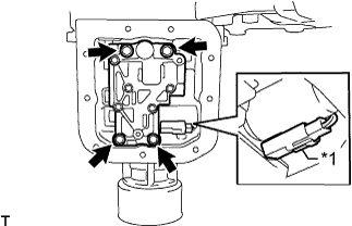
Text in Illustration *1 Transfer Transmission Wire O-ring 
Coat with Toyota Genuine ATF WS Coat the transfer transmission wire O-ring with ATF.
ATF Toyota Genuine ATF WS -
Install the transfer transmission wire with the bolt.
- Torque:
- 5.4 N*m { 55 kgf*cm, 48 in.*lbf }
-
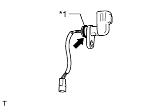
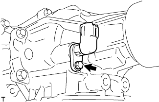
Text in Illustration *1 Connector Connect the connector to the transfer control solenoid assembly.
-
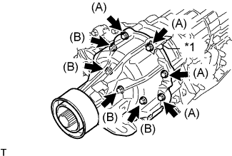
Install the transfer control valve body assembly with the 4 bolts.
- Torque:
- 9.8 N*m { 100 kgf*cm, 87 in.*lbf }
-
-
INSTALL TRANSFER OIL PAN SUB-ASSEMBLY
-
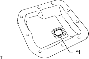
Text in Illustration *1 Transfer Oil Cleaner Magnet Install the transfer oil cleaner magnet to the transfer oil pan sub-assembly.
-
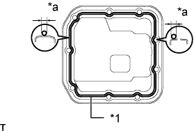
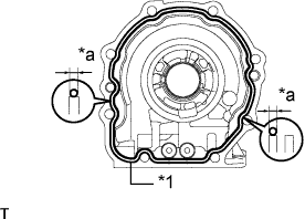
Text in Illustration *1 Seal Packing *a Seal Width 3.0 to 3.5 mm (0.12 to 0.14 in.) Clean the threads of the bolts and the transfer oil pan sub-assembly with non-residue solvent.
-
Apply seal packing to the transfer oil pan sub-assembly as shown in the illustration.
Seal packing Toyota Genuine Seal Packing 1281, Three Bond 1281 or equivalent Note
Reassemble the parts within 5 minutes of applying fresh FIPG material. Otherwise, the packing (FIPG) material must be removed and reapplied.
-
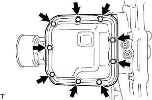
Temporarily install the 9 bolts in several steps, and then tighten them to the specified torque.
- Torque:
- 7.4 N*m { 75 kgf*cm, 65 in.*lbf }
-