TRANSFER ASSEMBLY DISASSEMBLY

-
REMOVE TRANSFER OIL PAN SUB-ASSEMBLY
-
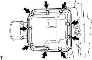
Remove the 9 bolts.
-
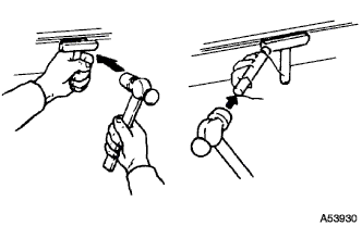
Insert the blade of an oil pan seal cutter between the transfer oil pan sub-assembly and transfer case sub-assembly. Cut through the sealer and remove the transfer oil pan sub-assembly.
Note
Do not damage the contact surface of the transfer oil pan sub-assembly.
-
Remove the transfer oil cleaner magnet from the transfer oil pan sub-assembly.
Note
-
Clean the inside of the transfer oil pan sub-assembly thoroughly, removing all metal shavings, sludge and any other foreign objects.
-
Remove any metal shavings from the transfer oil cleaner magnet.
-
-
-
REMOVE TRANSFER CONTROL VALVE BODY ASSEMBLY
-
Remove the 4 bolts and the transfer control valve body assembly.
-
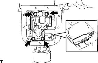
Text in Illustration *1 Connector Disconnect the connector from the transfer control solenoid assembly.
-
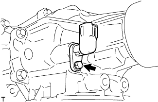
Remove the bolt and the transfer transmission wire.
-
-
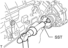
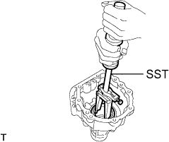
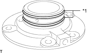
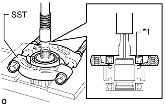
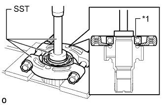
REMOVE TRANSFER EXTENSION HOUSING DUST DEFLECTOR
-
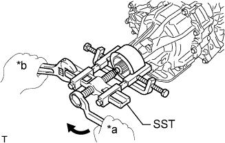
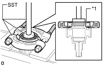
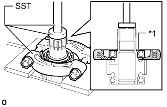
Text in Illustration *a Turn *b Hold Using SST, remove the transfer extension housing dust deflector.
- SST
- 09950-40011 ( 09951-04010, 09952-04010, 09953-04020, 09954-04010, 09955-04051, 09958-04011 )
Note
Apply grease to the threads and tip of SST center bolt before use.
-
-
REMOVE TRANSFER CASE SUB-ASSEMBLY
-
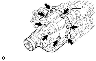
Text in Illustration *1 Clamp Remove the 8 bolts and clamp.
-
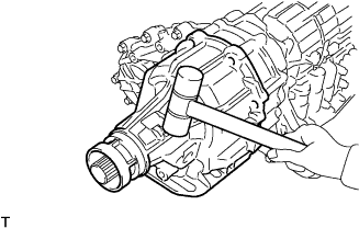
Using a plastic-faced hammer, tap the transfer case sub-assembly to remove it.
-
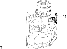
Text in Illustration *1 Clamp Remove the bolt and clamp.
-
-
REMOVE TRANSFER REAR OUTPUT SHAFT ASSEMBLY
-
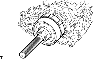
Remove the transfer rear output shaft assembly.
-
-
REMOVE FLANGE YOKE ASSEMBLY
-
Using SST and a hammer, release the staked part of the flange yoke nut.
- SST
- 09930-00010
Note
-
Be sure to use SST with the tapered surface facing the shaft.
-
Do not grind the tip of SST with a grinder, etc.
-
Completely loosen the staked part of the flange yoke nut when removing it.
-
Do not damage the threads of the transfer drive sprocket.
-
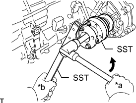
Text in Illustration *a Turn *b Hold Using SST, hold the flange yoke assembly.
- SST
- 09213-54015 ( 91651-60855 )
- 09330-00021
-
Using a 30 mm deep socket wrench, remove the flange yoke nut.
-
Remove the flange yoke assembly.
-
-
REMOVE TRANSFER REAR CHAIN CASE ASSEMBLY
-
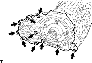
Remove the 10 bolts.
-
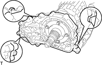
Tap the 3 protrusions of the transfer rear chain case assembly gently with a brass bar and hammer to loosen, and remove it.
Note
Do not damage the transfer rear chain case assembly.
-
-
REMOVE TRANSFER FRONT DRIVE CHAIN, TRANSFER DRIVE SPROCKET SUB-ASSEMBLY AND TRANSFER FRONT DRIVE CLUTCH SLEEVE SUB-ASSEMBLY
-
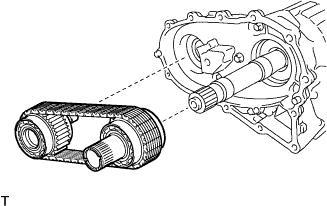
Remove the transfer front drive chain, transfer drive sprocket sub-assembly and transfer front drive clutch sleeve sub-assembly.
-
Remove the transfer front drive chain from the transfer drive sprocket sub-assembly and transfer front drive clutch sleeve sub-assembly.
-
-
REMOVE TRANSFER FRONT CHAIN CASE
-
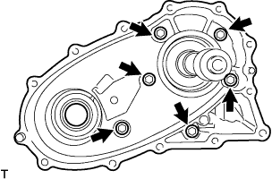
Remove the 6 bolts and transfer front chain case.
Tech Tips
If necessary, tap the transfer front chain case with a plastic-faced hammer to loosen and remove it.
-
-
REMOVE TRANSFER CASE OIL SEAL
-
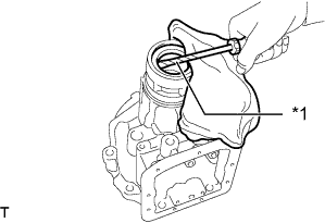
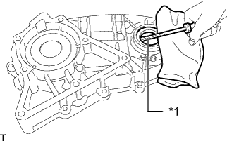
Text in Illustration *1 Protective Tape Using a screwdriver with its tip taped, pry out the transfer case oil seal from the transfer case sub-assembly.
-
-
REMOVE TRANSFER CASE BEARING
-
Using SST, remove the transfer case bearing from the transfer case sub-assembly.
- SST
- 09308-00010
-
-
REMOVE TRANSFER BAFFLE VALVE SUB-ASSEMBLY
-
Remove the bolt and transfer baffle valve sub-assembly from the transfer rear chain case assembly.
-
-
REMOVE TRANSFER CHAIN CASE GOVERNOR APPLY GASKET
-
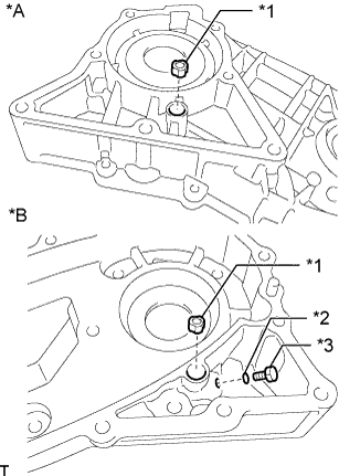
Text in Illustration *A for Front Side *B for Rear Side *1 Transfer Chain Case Governor Apply Gasket *2 O-ring *3 Screw Remove the screw, O-ring, and 2 transfer chain case governor apply gaskets from the transfer front chain case.
-
Remove the 2 transfer chain case governor apply gaskets from the transfer rear chain case assembly.
-
-
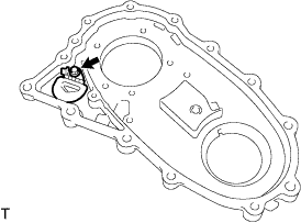
REMOVE TRANSFER CHAIN CASE OIL SEAL
-
Text in Illustration *1 Protective Tape Using a screwdriver with its tip taped, pry out the transfer chain case oil seal from the transfer front chain case.
-
-
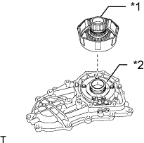
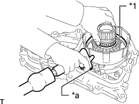
REMOVE TRANSFER REAR OUTPUT SHAFT ASSEMBLY AND CENTER DIFFERENTIAL CARRIER ASSEMBLY
-
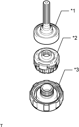
Text in Illustration *1 Transfer Rear Output Shaft Assembly *2 Center Differential Carrier Assembly *3 Transfer Direct Clutch Drum Sub-assembly Remove the transfer rear output shaft assembly and center differential carrier assembly from the transfer direct clutch drum sub-assembly.
-
-
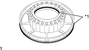
REMOVE TRANSFER REAR OUTPUT SHAFT BEARING
-
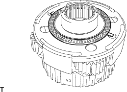
Remove the transfer rear output shaft bearing from the center differential carrier assembly.
-
-
REMOVE CENTER DIFFERENTIAL CLUTCH DISC SET
-
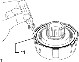
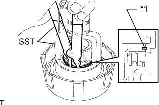
Text in Illustration *1 Protective Tape Using a screwdriver with its tip taped, remove the transfer direct clutch flange snap ring from the transfer direct clutch drum sub-assembly.
-
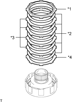
Text in Illustration *1 Center differential clutch disc flange (No. 1) *2 Center differential clutch disc set (Discs) *3 Center differential clutch disc set (Plates) *4 Center differential clutch disc flange (No. 2) Remove the 2 center differential clutch disc flanges and center differential clutch disc set from the transfer direct clutch drum sub-assembly.
-
-
REMOVE CENTER DIFFERENTIAL CLUTCH PRESSURE BALANCER
-
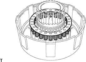
Text in Illustration *1 Transfer Direct Clutch Return Spring Snap Ring Place SST on the center differential clutch pressure balancer and compress the transfer direct clutch return spring assembly with a press.
- SST
- 09350-30020 ( 09350-07040 )
-
Using SST, remove the transfer direct clutch return spring snap ring.
- SST
- 09350-30020 ( 09350-07040, 09350-07070 )
-
Remove the center differential clutch pressure balancer from the transfer direct clutch drum sub-assembly.
-
-
REMOVE TRANSFER DIRECT CLUTCH RETURN SPRING ASSEMBLY
-
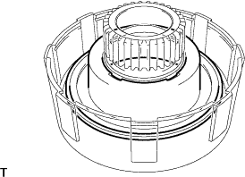
Remove the transfer direct clutch return spring assembly from the transfer direct clutch drum sub-assembly.
-
-
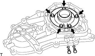
REMOVE CENTER DIFFERENTIAL CLUTCH PISTON
-
Text in Illustration *1 Transfer Direct Clutch Drum Sub-assembly *2 Transfer Center Support Assembly Install the transfer direct clutch drum sub-assembly to the transfer center support assembly.
-
Text in Illustration *1 Center Differential Clutch Piston *a Oil Hole While pushing down evenly on the center differential clutch piston, apply air (200 kPa, 2.0 kgf/cm2, 19 psi) at the oil hole on the transfer rear chain case assembly as shown in the illustration to remove the center differential clutch piston from the transfer direct clutch drum sub-assembly.
-
Remove the transfer direct clutch drum sub-assembly from the transfer center support assembly.
-
-
REMOVE TRANSFER DIRECT CLUTCH PISTON O-RING
-
Text in Illustration *1 Transfer Direct Clutch Piston O-ring Remove the 2 transfer direct clutch piston O-rings from the center differential clutch piston.
-
-
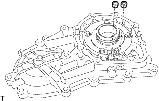
REMOVE TRANSFER CENTER SUPPORT ASSEMBLY
-
Remove the 5 bolts and transfer center support assembly.
-
Remove the 2 screws and 2 O-rings from the transfer rear chain case assembly.
-
-
REMOVE TRANSFER CENTER SUPPORT SEAL RING
-
Text in Illustration *1 Transfer Center Support Seal Ring Remove the 2 transfer center support seal rings from the transfer center support assembly.
-
-
REMOVE TRANSFER DRIVEN SPROCKET BEARING
-
Text in Illustration *1 Transfer Driven Sprocket Bearing Using SST and a press, remove the transfer driven sprocket bearing from the transfer front drive clutch sleeve sub-assembly.
- SST
- 09950-00020
-
Text in Illustration *1 Transfer Driven Sprocket Bearing Using SST and a press, remove the transfer driven sprocket bearing from the transfer front drive clutch sleeve sub-assembly.
- SST
- 09950-00020
- 09950-60010 ( 09951-00530 )
- 09950-70010 ( 09951-07100 )
-
-
REMOVE TRANSFER DRIVE SPROCKET BEARING
-
Text in Illustration *1 Transfer Drive Sprocket Bearing Using SST and a press, remove the transfer drive sprocket bearing from the transfer drive sprocket sub-assembly.
- SST
- 09950-00020
- 09950-60010 ( 09951-00480 )
- 09950-70010 ( 09951-07100 )
-
Text in Illustration *1 Transfer Drive Sprocket Bearing Using SST and a press, remove the transfer drive sprocket bearing from the transfer drive sprocket sub-assembly.
- SST
- 09950-00020
- 09950-60010 ( 09951-00530 )
- 09950-70010 ( 09951-07100 )
-
-
REMOVE TRANSFER CONTROL SOLENOID ASSEMBLY
-
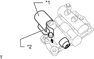
Text in Illustration *1 Transfer Control Solenoid Assembly *2 Solenoid Lock Plate Remove the bolt, solenoid lock plate and transfer control solenoid assembly.
-