AUTOMATIC TRANSMISSION ASSEMBLY INSTALLATION

-
INSTALL TORQUE CONVERTER CLUTCH ASSEMBLY
-
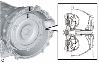
Attach the splines of the input shaft and turbine runner.
-
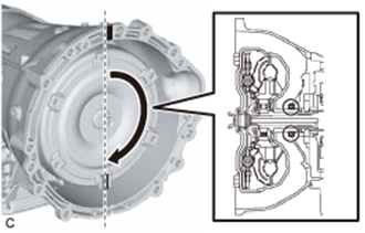
Attach the splines of the stator shaft and stator while turning the torque converter assembly.
Tech Tips
If the stator shaft splines are difficult to engage with the stator splines, move the torque converter back approximately 10 mm (0.393 in.) and engage the splines while rotating the torque converter assembly.
-
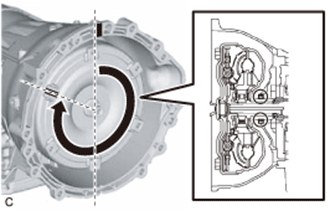
Turn the torque converter to engage the key of the oil pump drive gear with the slot on the torque converter assembly.
-
Clean the torque converter set bolt holes.
-
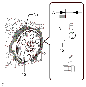
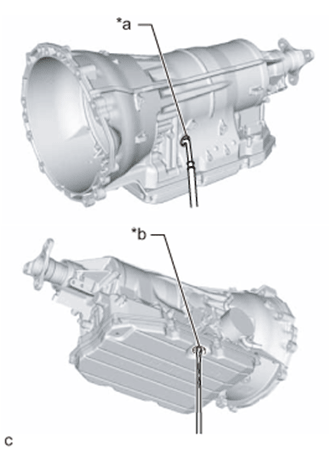
Text in Illustration *a Engine Surface *b Drive Plate Surface Using a vernier caliper and straightedge, measure dimension A between the transmission contact surface of the engine and the torque converter contact surface of the drive plate.
Note
Make sure to deduct the thickness of the straightedge.
-
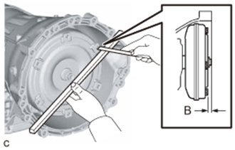
Using a vernier caliper and straightedge, measure dimension B shown in the illustration and check that dimension B is more than dimension A, which was measured in the previous step.
Standard A + 1 mm (0.0394 in.) or more Note
-
Make sure to deduct the thickness of the straightedge.
-
If the transaxle is installed to the engine with the torque converter not sufficiently inserted, the torque converter may be damaged.
-
-
-
INSTALL REAR ENGINE MOUNTING BRACKET
-
Install the rear engine mounting bracket to the automatic transmission assembly with the 4 bolts.
- Torque:
- 40 N*m { 408 kgf*cm, 30 ft.*lbf }
-
-
INSTALL REAR ENGINE MOUNTING INSULATOR
-
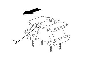
Text in Illustration *a Claw 
Front of the Vehicle Install the rear engine mounting insulator to the rear engine mounting bracket with the 4 bolts.
- Torque:
- 13 N*m { 133 kgf*cm, 10 ft.*lbf }
Tech Tips
Make sure the claw is facing towards the front of the vehicle.
-
-
INSTALL AUTOMATIC TRANSMISSION ASSEMBLY
-
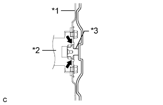
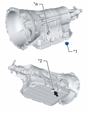
Text in Illustration *1 Drive Plate *2 Crankshaft *3 Torque Converter Centerpiece Apply clutch spline grease to the circumference of the crankshaft contact surface with the torque converter centerpiece.
Clutch spline grease Toyota Genuine Clutch Spline Grease or equivalent Maximum spread About 1 g (0.0353 oz.) -
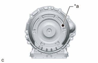
Text in Illustration *a Mark Make sure that the mark is positioned as shown in the illustration.
-
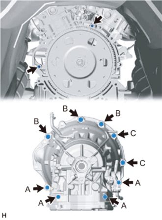
Confirm that the 2 knock pins are installed on the engine assembly and are not damaged.
- Torque:
- for Bolt A
- 37 N*m { 377 kgf*cm, 27 ft.*lbf }
- for Bolt B and C
- 71 N*m { 724 kgf*cm, 52 ft.*lbf }
Note
-
When tightening the bolts, be sure that the contact surfaces of the engine assembly and the automatic transmission assembly are in close contact with one another.
-
Do not forcibly pry on the automatic transmission assembly.
-
Check that the torque converter assembly rotates.
-
Make sure not to pinch or damage any wire harness.
-
In order to protect the automatic transmission oil pan sub-assembly, place attachments on the transmission jack.
-
Make sure that the attachments and the automatic transmission oil pan sub-assembly are centered on the transmission jack.
-
To prevent the automatic transmission oil pan sub-assembly from deforming, do not place any attachments under the automatic transmission oil pan sub-assembly of the automatic transmission assembly.
-
Secure the automatic transmission assembly to the transmission jack using a belt, etc. to prevent it from falling.
Tech Tips
-
Bolt A: 43 mm (1.69 in.)
-
Bolt B: 50 mm (1.97 in.)
-
Bolt C: 70 mm (2.76 in.)
Bolt length
-
-
CONNECT WATER BY-PASS HOSE (w/ ATF Warmer)
-
Tilt down the automatic transmission assembly.
Note
Make sure that the cooling fan and fan shroud do not contact the engine assembly when tilting the automatic transmission assembly.
-
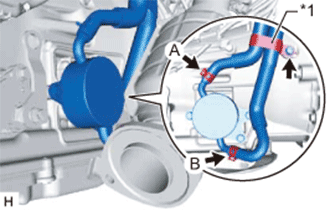
Text in Illustration *1 Hose Clamp Connect the water by-pass hose and No. 2 water by-pass hose to the transmission oil cooler and slide the 2 clips to secure them.
Note
Make sure that the claws marked A in the illustration are facing toward the top of the vehicle, and that the claws marked B in the illustration are facing toward the underside of the vehicle.
-
Install the hose clamp to the automatic transmission assembly with the bolt.
- Torque:
- 20 N*m { 204 kgf*cm, 15 ft.*lbf }
-
-
CONNECT OIL COOLER TUBE SUB-ASSEMBLY (w/o ATF Warmer)
-
Tilt down the automatic transmission assembly.
Note
Make sure that the cooling fan and fan shroud do not contact the engine assembly when tilting the automatic transmission assembly.
-
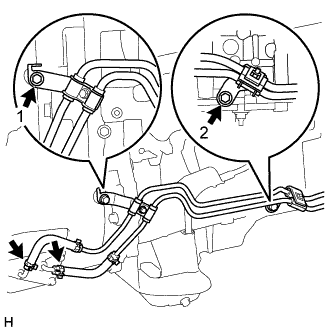
Connect the 2 oil cooler hoses to the automatic transmission assembly and slide the 2 clips to secure them.
Note
Make sure the pinching portion of each clip is facing toward the RH side of the vehicle.
-
Temporarily install the oil cooler tube sub-assembly with the 2 bolts.
-
Tighten the bolts in the order shown in the illustration.
- Torque:
- 22 N*m { 224 kgf*cm, 16 ft.*lbf }
-
-
CONNECT WIRE HARNESS
-
Connect the park/neutral position switch assembly connector.
-
Connect the transmission wire connector.
Tech Tips
Push up the lever until the claw of the transmission wire connector makes a connection sound.
-
Install the wire harness to the automatic transmission assembly with the 4 clamps and nut.
- Torque:
- 10 N*m { 102 kgf*cm, 7 ft.*lbf }
-
Connect the breather plug hose.
-
-
CONNECT NO. 2 GROUND WIRE
-
Install the No. 2 ground wire to the automatic transmission assembly with the bolt.
- Torque:
- 10 N*m { 102 kgf*cm, 7 ft.*lbf }
-
-
INSTALL REAR ENGINE MOUNTING MEMBER
-
Tilt up the automatic transmission assembly.
-
Install the rear engine mounting member to the body with the 4 bolts.
- Torque:
- 35 N*m { 354 kgf*cm, 26 ft.*lbf }
-
Install the 4 nuts and connect the rear engine mounting member to the automatic transmission assembly.
- Torque:
- 13 N*m { 133 kgf*cm, 10 ft.*lbf }
-
-
INSTALL FLOOR SHIFT GEAR SHIFTING ROD SUB-ASSEMBLY
-
Install the floor shift gear shifting rod sub-assembly to the transmission control shaft lever RH with the pin.
-
Install a new clip.
-
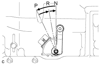
Turn the transmission control shaft lever RH of the park/neutral position switch assembly counterclockwise until it stops, and then turn it clockwise 2 notches to set it to the N position.
-
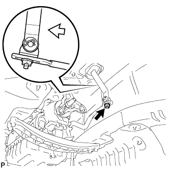
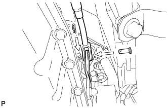
Move the shift lever to N and tighten the nut while lightly pushing the lever toward R.
Text in Illustration 
Pushing the lever rearward Note
Do not push the shift lever too hard.
-
After adjustment, check that the shift lever moves smoothly and the shift lever and gear operate correctly.
-
Connect the floor shift gear shifting rod sub-assembly with the nut.
- Torque:
- 13 N*m { 130 kgf*cm, 9 ft.*lbf }
Note
Do not push the shift lever too hard.
-
-
INSTALL DRIVE PLATE AND TORQUE CONVERTER CLUTCH SETTING BOLT
-
Using SST, hold the crankshaft pulley.
- SST
- 09213-70011 ( 09213-70020 )
- 09330-00021
-
Install the 6 drive plate and torque converter setting bolts.
- Torque:
- 41 N*m { 418 kgf*cm, 30 ft.*lbf }
Note
Install the black colored bolt first, and then the 5 silver colored bolts.
-
-
INSTALL FLYWHEEL HOUSING SIDE COVER
-
Install the flywheel housing side cover to the engine assembly.
Note
Make sure that the flywheel housing side cover is securely installed.
-
-
INSTALL STARTER ASSEMBLY
-
INSTALL NO. 1 EXHAUST PIPE SUPPORT BRACKET SUB-ASSEMBLY
-
Install the No. 1 exhaust pipe support bracket sub-assembly with the 2 bolts.
- Torque:
- 43 N*m { 438 kgf*cm, 32 ft.*lbf }
-
-
INSTALL FRONT CENTER FLOOR BRACE SUB-ASSEMBLY
-
Install the front center floor brace with the 2 clips, 6 bolts and 2 nuts.
- Torque:
- 19 N*m { 194 kgf*cm, 14 ft.*lbf }
-
-
INSTALL PROPELLER SHAFT WITH CENTER BEARING ASSEMBLY
-
INSTALL INTAKE AIR SURGE TANK ASSEMBLY
-
CONNECT CABLE TO NEGATIVE BATTERY TERMINAL
Note
When disconnecting the cable, some systems need to be initialized after the cable is reconnected Click here.
-
ADD AUTOMATIC TRANSMISSION FLUID
-
Lift the vehicle.
Note
Set the vehicle on a lift so that the vehicle is kept level when it is lifted up (make sure that the tilt angle from the front to rear of the vehicle is within +/-1°).
-
Text in Illustration *1 Refill Plug *2 Overflow Plug *a Refill Hole Remove the refill plug and O-ring.
-
Using a 5 mm hexagon socket wrench, remove the overflow plug and gasket.
-
Text in Illustration *a Refill Hole *b Overflow Hole Add fluid to the refill hole until it flows out of the overflow hole.
Note
-
Use Toyota Genuine ATF WS.
-
Be sure to add automatic transmission fluid slowly. If fluid is added quickly, the fluid may hit internal parts and bounce back, resulting in fluid coming out of the refill hole.
-
-
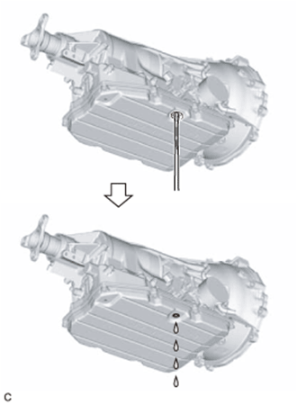
Wait until the fluid flow slows and only drips come out.
-
Using a 5 mm hexagon socket wrench, temporarily install the overflow plug and gasket.
Tech Tips
Reuse the old gasket as the overflow plug will be removed again.
-
-
ADD ENGINE COOLANT
-
INSPECT FOR ENGINE COOLANT LEAK
CAUTION:
Do not remove the radiator cap while the engine and radiator are still hot. Pressurized hot engine coolant and steam may be released and cause serious burns.
Note
Before performing each inspection, turn the A/C switch off.
-
Fill the radiator with coolant and attach a radiator cap tester.
-
Warm up the engine.
-
Using a radiator cap tester, increase the pressure inside the radiator to 137 kPa (1.4 kgf/cm2, 20 psi), and check that the pressure does not drop.
If the pressure drops, check the hoses, radiator and water pump for leaks. If no external leaks are found, check the heater core, cylinder block and cylinder head.
-
-
ADJUST AUTOMATIC TRANSMISSION FLUID
-
INSPECT FOR EXHAUST GAS LEAK
If gas is leaking, tighten the areas necessary to stop the leak. Replace damaged parts as necessary.
Tech Tips
If an exhaust gas leak has been repaired, perform an inspection following the repair Click here.
-
INSPECT SHIFT LEVER POSITION
-
When moving the shift lever from P to R with the engine switch on (IG) and the brake pedal depressed, make sure that the shift lever moves smoothly and correctly into the position.
-
Start the engine and make sure that the vehicle moves forward when moving the shift lever from N to D and moves rearward when moving the shift lever to R.
If the operation cannot be done as specified, inspect the park/neutral position switch assembly and check the shift lever assembly installation condition.
-
-
INSTALL NO. 2 ENGINE UNDER COVER
-
Install the No. 2 engine under cover with the 4 screws.
-
-
INSTALL FRONT SUSPENSION MEMBER BRACE
-
Install the front suspension member brace with the clip and 4 bolts.
- Torque:
- 52 N*m { 530 kgf*cm, 38 ft.*lbf }
-
-
RESET MEMORY