OIL PUMP INSPECTION

-
INSPECT STATOR SHAFT SPRING SUB-ASSEMBLY
-
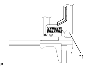
Text in Illustration *1 Straightedge Using a vernier caliper and straightedge, measure the distance between the stator shaft spring sub-assembly end and the straightedge.
Standard thickness 6.52 mm (0.257 in.)
-
-
INSPECT FRONT OIL PUMP BODY SUB-ASSEMBLY
-
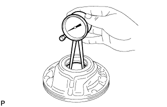
Using a caliper gauge, measure the inside diameter of the front oil pump body sub-assembly bushing.
Maximum inside diameter 45.078 mm (1.7747 in.) If the inside diameter is more than the maximum, replace the front oil pump body sub-assembly.
-
-
INSPECT STATOR SHAFT ASSEMBLY
-
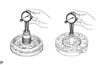
Using a caliper gauge, measure the inside diameter of the stator shaft assembly bushing.
Maximum inside diameter Front side 21.527 mm (0.8475 in.) Rear side 35.251 mm (1.3878 in.) If the inside diameter is more than the maximum, replace the stator shaft assembly.
-
-
INSPECT CLEARANCE OF OIL PUMP ASSEMBLY
-
Push the driven gear to one side of the pump body.
-
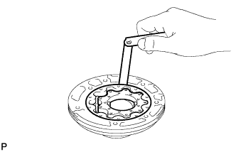
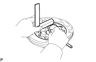
Using a feeler gauge, measure the clearance between the front oil pump driven gear and front oil pump body sub-assembly.
Standard body clearance 0.10 to 0.17 mm (0.00394 to 0.00669 in.) If the body clearance is not as specified, replace the front oil pump drive gear, front oil pump driven gear and pump body sub-assembly.
-
Using a feeler gauge, measure the clearance between the driven gear teeth and drive gear teeth.
Standard tip clearance 0.07 to 0.15 mm (0.00276 to 0.00590 in.) If the tip clearance is not as specified, replace the drive gear, driven gear and pump body.
-
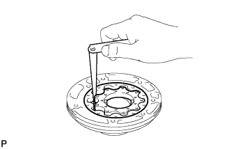
Using a steel straightedge and feeler gauge, measure the clearance between both gears and the straightedge.
Standard side clearance 0.03 to 0.05 mm (0.00119 to 0.00196 in.) If the side clearance is not as specified, replace the drive gear, driven gear and pump body.
Tech Tips
There are 7 different thicknesses for the drive and driven gears.
Front Oil Pump Drive Gear Thickness Part No. Mark Thickness 35321-50080 0 11.636 to 11.642 mm (0.4582 to 0.4583 in.) 35321-50090 1 11.643 to 11.649 mm (0.4584 to 0.4586 in.) 35321-50100 2 11.650 to 11.656 mm (0.4587 to 0.4588 in.) 35321-50110 3 11.657 to 11.663 mm (0.4590 to 0.4591 in.) 35321-50120 4 11.664 to 11.670 mm (0.4593 to 0.4594 in.) 35321-50130 5 11.671 to 11.677 mm (0.4595 to 0.4597 in.) 35321-50140 6 11.678 to 11.684 mm (0.4598 to 0.4599 in.) Front Oil Pump Driven Gear Thickness Part No. Mark Thickness 35322-50080 0 11.636 to 11.642 mm (0.4582 to 0.4583 in.) 35322-50090 1 11.643 to 11.649 mm (0.4584 to 0.4586 in.) 35322-50100 2 11.650 to 11.656 mm (0.4587 to 0.4588 in.) 35322-50110 3 11.657 to 11.663 mm (0.4590 to 0.4591 in.) 35322-50120 4 11.664 to 11.670 mm (0.4593 to 0.4594 in.) 35322-50130 5 11.671 to 11.677 mm (0.4595 to 0.4597 in.) 35322-50140 6 11.678 to 11.684 mm (0.4598 to 0.4599 in.)
-
-
INSPECT OIL PUMP DRIVE GEAR ROTATION
-
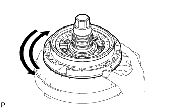
Place the oil pump assembly on the torque converter clutch.
-
Make sure that the drive gear rotates smoothly.
-