AUTOMATIC TRANSMISSION SYSTEM Kick Down Switch Circuit
DESCRIPTION
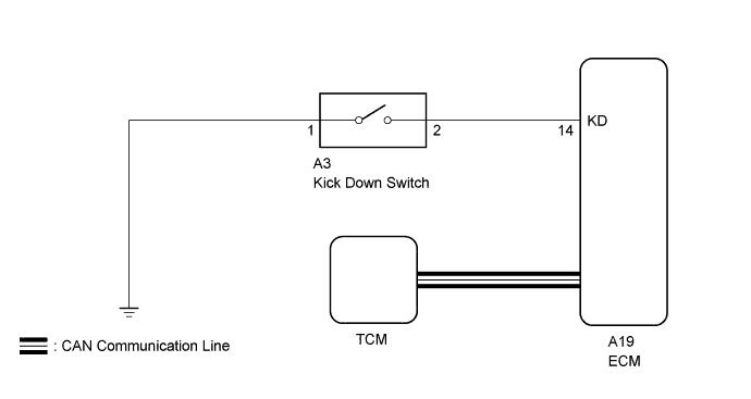
The kick-down switch turns ON when the accelerator pedal is fully depressed to send a signal to the ECM.
When the kick-down switch is ON, the ECM controls gear shifting according to programmed shift diagrams.
If a short circuit develops in the kick-down switch, the ECM disregards the kick-down signals and controls shifting at the normal shift points.
WIRING DIAGRAM
INSPECTION PROCEDURE
PROCEDURE
-
CHECK HARNESS AND CONNECTOR (KICK DOWN SWITCH - BODY GROUND)
-
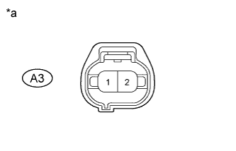
Text in Illustration *a Front view of wire harness connector
(to Kick Down Switch Assembly)
Disconnect the kick-down switch connector.
-
Measure the resistance according to the value(s) in the table below.
Standard Resistance Tester Connection Condition Specified Condition A3-1 - Body ground Always Below 1 Ω
NG 
REPAIR OR REPLACE HARNESS OR CONNECTOR
OK 
-
-
INSPECT KICK DOWN SWITCH ASSEMBLY
-
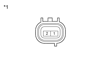
Text in Illustration *1 Kick Down Switch Assembly Remove the kick-down switch assembly Click here.
-
Measure the resistance according to the value(s) in the table below.
Standard Resistance Tester Connection Switch Condition Specified Condition 2 - 1 Continuously press
(Kick-down switch is ON)
Below 1 Ω 2 - 1 Released
(Kick-down switch is OFF)
10 kΩ or higher
NG
REPLACE KICK DOWN SWITCH ASSEMBLY Click here
OK
-
-
CHECK HARNESS AND CONNECTOR (KICK DOWN SWITCH - ECM)
-
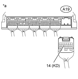
Text in Illustration *a Rear view of wire harness connector
(to ECM)
Disconnect the ECM connector.
-
Measure resistance according to the value(s) in the table below.
Standard Resistance Tester Connection Condition Specified Condition A19-14 (KD) - Body ground Fully depressed
(Kick-down switch is ON)
Below 1 Ω A19-14 (KD) - Body ground Release
(Kick-down switch is OFF)
10 kΩ or higher
NG
REPAIR OR REPLACE HARNESS OR CONNECTOR
OK 
PROCEED TO NEXT SUSPECTED AREA SHOWN IN PROBLEM SYMPTOMS TABLE Click here
-