AUTOMATIC TRANSMISSION SYSTEM, Diagnostic DTC:P0873

| DTC Code | DTC Name |
|---|---|
| P0873 | Transmission Fluid Pressure Sensor / Switch "C" Circuit High |
DESCRIPTION
The oil pressure switch, which is built into the valve body, detects the fluid pressure of the SL1 fluid pressure circuit. If shift solenoid valve SL1 is stuck ON, P0873 is output.
| DTC No. | DTC Detection Condition
|
Trouble Area |
|---|---|---|
| P0873 |
|
|
WIRING DIAGRAM
Refer to DTC P0872 Click here.
INSPECTION PROCEDURE
Note
Perform registration and/or initialization when parts related to the automatic transmission are replaced Click here.
PROCEDURE
-
READ VALUE USING GTS (TPS 1 SWITCH)
-
Connect the GTS to the DLC3.
-
Turn the engine switch on (IG).
-
Turn the GTS on.
-
Enter the following menus: Powertrain / ECT / Active Test / Control the Shift Position.
ECT Tester Display Test Part Control Range Diagnostic Note Control the Shift Position Operates the shift solenoid valves to allow gears to be selected manually
-
Press "→" button: Up-shift occurs
-
Press "←" button: Down-shift occurs
Possible to check operation of the shift solenoid valves.
[Vehicle Condition]
-
Vehicle speed: 50 km/h (31 mph) or less
-
-
Select TPS 1 Switch in the Data List.
-
While performing the "Control the Shift Position" Active Test, check TPS 1 Switch in the Data List.
ECT Tester Display Measurement Item/Range Normal Condition Diagnostic Note TPS 1 Switch Oil pressure switch status/
ON or OFF
-
ON: Gear is 1st to 5th
-
OFF: Gear is 6th to 8th, or shift lever is in P, N or R
- Result Result Proceed to When the engine is idling with the shift lever in P, N or R, ON is displayed for TPS 1 Switch on the Data List. A When the vehicle is being driven in a gear position between 6th and 8th or when the engine is idling with the shift lever in P, N or R, OFF is displayed for TPS 1 Switch on the Data List. B When the vehicle is being driven in a gear position between 6th and 8th, ON is displayed for TPS 1 Switch on the Data List. C -
B 
REPLACE TCM Click here
C
CHECK HARNESS AND CONNECTOR (TRANSMISSION WIRE - TCM) Click here
A 
-
-
CHECK OIL PRESSURE SWITCH CIRCUIT
Tech Tips
Before checking, perform visual and contact pressure checks on the TCM connectors.
-
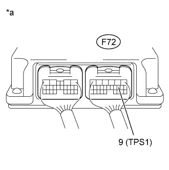
Text in Illustration *a Component with harness connected
(TCM)
Measure the resistance according to the value(s) in the table below.
Standard Resistance Tester Connection Switch Condition Specified Condition F72-9 (TPS1) - Body ground Engine switch off 10 kΩ or higher
NG
CHECK HARNESS AND CONNECTOR (TCM - BODY GROUND) Click here
OK
-
-
INSPECT SHIFT SOLENOID VALVE SL1
-
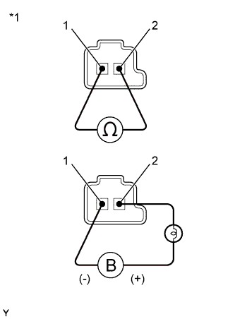
Text in Illustration *1 Shift Solenoid Valve SL1 Remove the shift solenoid valve SL1 Click here.
-
Measure the resistance according to the value(s) in the table below.
Standard Resistance Tester Connection Condition Specified Condition Terminal 1 of the shift solenoid valve SL1 - Terminal 2 20°C (68°F) 5.0 to 5.6 Ω -
Connect a positive (+) battery lead with a 21 W bulb to terminal 2 and a negative (-) battery lead to terminal 1 of the solenoid valve connector. Then check that the valve moves and makes an operating sound.
OK Valve moves and makes an operating sound.
NG 
REPLACE SHIFT SOLENOID VALVE SL1 Click here
OK
-
-
INSPECT TRANSMISSION VALVE BODY ASSEMBLY
-
Check the transmission valve body assembly Click here.
OK There is no foreign matter on each valve and they operate smoothly.
NG
REPAIR OR REPLACE TRANSMISSION VALVE BODY ASSEMBLY Click here
OK 
REPAIR OR REPLACE AUTOMATIC TRANSMISSION ASSEMBLY Click here
-
-
CHECK HARNESS AND CONNECTOR (TCM - BODY GROUND)
-
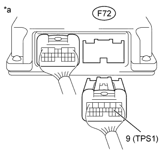
Text in Illustration *a Rear view of wire harness connector
(to TCM)
Disconnect the TCM connector.
-
Measure the resistance according to the value(s) in the table below.
Standard Resistance Tester Connection Switch Condition Specified Condition F72-9 (TPS1) - Body ground Engine switch off 10 kΩ or higher
NG
CHECK HARNESS AND CONNECTOR (TRANSMISSION WIRE - TCM) Click here
OK
-
-
REPLACE TCM
-
Replace the TCM Click here.
NEXT
PERFORM A/T CODE REGISTRATION Click here
-
-
CHECK HARNESS AND CONNECTOR (TRANSMISSION WIRE - TCM)
-
Disconnect the F73 transmission wire connector.
-
Disconnect the F72 TCM connector.
-
Measure the resistance according to the value(s) in the table below.
Standard Resistance Tester Connection Condition Specified Condition F73-17 (TPS1) - F72-9 (TPS1) Always Below 1 Ω F73-17 (TPS1) or F72-9 (TPS1) - Body ground Always 10 kΩ or higher
NG
REPAIR OR REPLACE HARNESS OR CONNECTOR
OK
-
-
INSPECT TRANSMISSION WIRE (OIL PRESSURE SWITCH)
-
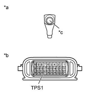
Text in Illustration *a Front view of wire harness connector
(to Oil Pressure Switch Connector)
*b Component without harness connected
(Transmission Wire)
*c Connector Disconnect the oil pressure switch connector Click here.
-
Disconnect the transmission wire connector.
-
Measure the resistance according to the value(s) in the table below.
Standard Resistance Tester Connection Condition Specified Condition Oil pressure switch connector - 17 (TPS1) Always Below 1 Ω Oil pressure switch connector or 17 (TPS1) - Body ground Always 10 kΩ or higher
NG
REPAIR OR REPLACE TRANSMISSION WIRE Click here
OK
REPLACE OIL PRESSURE SWITCH Click here
-