AUTOMATIC TRANSMISSION SYSTEM, Diagnostic DTC:P0711

| DTC Code | DTC Name |
|---|---|
| P0711 | Transmission Fluid Temperature Sensor "A" Performance |
DESCRIPTION
Refer to DTC P0712 Click here.
| DTC No. | DTC Detection Condition | Trouble Area |
|---|---|---|
| P0711 | Either condition is met (2-trip detection logic):
|
ATF temperature sensor (transmission wire) |
MONITOR DESCRIPTION
This DTC indicates that there is a problem with output from the ATF temperature sensor and that the sensor itself is defective. The ATF temperature sensor converts the ATF temperature to an electrical resistance value. Based on the resistance, the TCM determines the ATF temperature and detects open or short circuits in the ATF temperature sensor circuit or faults in the ATF temperature sensor.
After running the vehicle for a certain period, the ATF temperature should increase. If the ATF temperature is below 20°C (68°F) or 110°C (230°F) or higher after driving the vehicle for a certain period, the TCM interprets this as a fault, illuminates the MIL and stores the DTC.
WIRING DIAGRAM
Refer to DTC P0712 Click here.
INSPECTION PROCEDURE
Note
-
Perform registration and/or initialization when parts related to the automatic transmission are replaced Click here.
-
If DTCs P0711 and P2610 are output simultaneously, confirm that the ATF temperature is as specified in "Normal Condition" using the GTS first. When the ATF temperature is as specified in "Normal Condition", perform troubleshooting for DTC P2610 Click here.
-
DATA LIST
Note
In the table below, the values listed under "Normal Condition" are reference values.
Tech Tips
Using the GTS to read the Data List allows the values or states of switches, sensors, actuators and other items to be read without removing any parts. This non-intrusive inspection can be very useful because intermittent conditions or signals may be discovered before parts or wiring is disturbed. Reading the Data List information early in troubleshooting is one way to save diagnostic time.
-
Warm up the engine.
-
Turn the engine switch off.
-
Connect the GTS to the DLC3.
-
Turn the engine switch on (IG).
-
Turn the GTS on.
-
Enter the following menus: Powertrain / ECT / Data List / A/T Oil temperature 1.
-
According to the display on the GTS, read the Data List.
ECT Tester Display Measurement Item/Range Normal Condition Diagnostic Note A/T Oil Temperature 1 ATF temperature sensor value/
Min.: -40°C (-40°F)
Max.: 150°C (302°F)
-
After stall speed test: Approximately 80°C (176°F)
-
While engine is cold:
Equal to ambient temperature
If value is -40°C (-40°F) or 150°C (302°F), ATF temperature sensor circuit is open or short circuited. Tech Tips
-
When DTC P0712 is output and the GTS shows 150°C (302°F) or more, there is a short circuit.
-
When DTC P0713 is output and the GTS shows -40°C (-40°F), there is an open circuit.
Check the temperature displayed on the GTS in order to check if a malfunction exists.
Temperature Displayed Malfunction -40°C (-40°F) Open circuit 150°C (302°F) or more Short circuit Tech Tips
If a circuit related to the ATF temperature sensor becomes open, P0713 will be stored in approximately 0.5 seconds. It is not necessary to inspect the circuit when P0711 is output.
-
-
PROCEDURE
-
CHECK DTC OUTPUT (IN ADDITION TO DTC P0711 AND P0713)
-
Connect the GTS to the DLC3.
-
Turn the engine switch on (IG).
-
Turn the GTS on.
-
Enter the following menus: Powertrain / ECT / Trouble Codes.
-
Read the DTCs using the GTS.
Result Result Proceed to Only DTC P0711 is output A P0711 and P0713 are output B DTCs other than P0711 and P0713 are output C Tech Tips
If any other codes besides P0711 and P0713 are output, perform troubleshooting for those DTCs first.
B 
GO TO DTC P0713 FLOWCHART Click here
C
GO TO DTC CHART Click here
A 
-
-
CHECK TRANSMISSION FLUID LEVEL
-
Check the transmission fluid level Click here.
OK Automatic transmission fluid level is correct.
NG
ADJUST AUTOMATIC TRANSMISSION FLUID LEVEL Click here
OK
-
-
CHECK HARNESS AND CONNECTOR (ATF TEMPERATURE SENSOR - TCM)
-
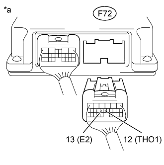
Text in Illustration *a Rear view of wire harness connector
(to TCM)
Disconnect the TCM connector.
-
Measure the resistance according to the value(s) in the table below.
Standard Resistance Tester Connection Condition Specified Condition F72-12 (THO1) - F72-13 (E2) ATF temperature 10°C (50°F) 5 to 8 kΩ F72-12 (THO1) - F72-13 (E2) ATF temperature 25°C (77°F) 2.5 to 4.5 kΩ F72-12 (THO1) - F72-13 (E2) ATF temperature 110°C (230°F) 0.22 to 0.28 kΩ Tech Tips
The resistance value for the 25°C (77°F) ATF temperature condition is a reference value.
-
Measure the resistance according to the value(s) in the table below.
Standard Resistance Tester Connection Condition Specified Condition F72-12 (THO1) - Body ground Always 10 kΩ or higher F72-13 (E2) - Body ground Always 10 kΩ or higher
NG 
CHECK HARNESS AND CONNECTOR (TRANSMISSION WIRE - TCM) Click here
OK
-
-
REPLACE TCM
-
Replace the TCM Click here.
NEXT 
PERFORM A/T CODE REGISTRATION Click here
-
-
CHECK HARNESS AND CONNECTOR (TRANSMISSION WIRE - TCM)
-
Disconnect the F73 transmission wire connector.
-
Disconnect the F72 TCM connector.
-
Measure the resistance according to the value(s) in the table below.
Standard Resistance Tester Connection Condition Specified Condition F73-8 (OIL) - F72-12 (THO1) Always Below 1 Ω F73-9 (E2) - F72-13 (E2) Always Below 1 Ω
NG
REPAIR OR REPLACE HARNESS OR CONNECTOR
OK
REPAIR OR REPLACE ATF TEMPERATURE SENSOR (TRANSMISSION WIRE) Click here
-