VEHICLE STABILITY CONTROL SYSTEM, Diagnostic DTC:C1279

| DTC Code | DTC Name |
|---|---|
| C1279 | Acceleration Sensor Output Voltage Malfunction (Test Mode DTC) |
DESCRIPTION
| DTC Code | DTC Detection Condition | Trouble Area |
|---|---|---|
| C1279 | Detected only during Test Mode. |
|
WIRING DIAGRAM
Refer to DTCs C1232, C1243 and C1245 Click here.
INSPECTION PROCEDURE
Note
When replacing the yaw rate sensor, perform zero point calibration Click here.
PROCEDURE
-
CHECK YAW RATE SENSOR INSTALLATION
-
Check that the yaw rate sensor has been installed properly Click here.
OK The sensor is tightened to the specified torque. The sensor is not installed in a tilted position.
NG 
INSTALL YAW RATE SENSOR CORRECTLY Click here
OK 
-
-
CHECK HARNESS AND CONNECTOR (IG TERMINAL)
-
Turn the engine switch off.
-
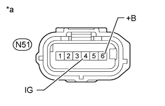
Text in Illustration *a Front view of wire harness connector
(to Yaw Rate Sensor)
Make sure that there is no looseness at the locking part and the connecting part of the connector.
-
Disconnect the yaw rate sensor connector.
-
Measure the voltage according to the value(s) in the table below.
Standard Voltage Tester Connection Condition Specified Condition N51-4 (IG) - Body ground Engine switch on (IG) 11 to 14 V N51-6 (+B) - Body ground Always 11 to 14 V
NG
REPAIR OR REPLACE HARNESS OR CONNECTOR
OK
-
-
CHECK HARNESS AND CONNECTOR (GND TERMINAL)
-
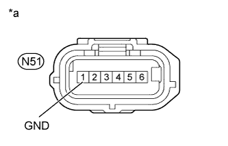
Text in Illustration *a Front view of wire harness connector
(to Yaw Rate Sensor)
Turn the engine switch off.
-
Disconnect the yaw rate sensor connector.
-
Measure the resistance according to the value(s) in the table below.
Standard Resistance Tester Connection Condition Specified Condition N51-1 (GND) - Body ground Always Below 1 Ω
NG
REPAIR OR REPLACE HARNESS OR CONNECTOR
OK 
REPLACE YAW RATE SENSOR Click here
-