SIDE TURN SIGNAL LIGHT ASSEMBLY REMOVAL

Tech Tips
-
Use the same procedure for the RH and LH sides.
-
The procedure described below is for the LH side.
-
REMOVE OUTER MIRROR (w/o Memory)
-
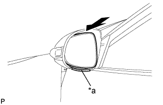
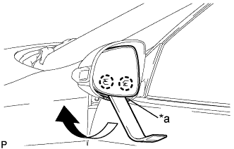
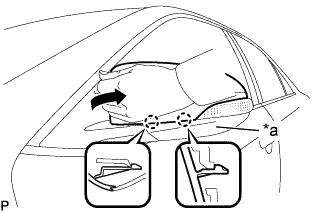
Text in Illustration *a Protective Tape Apply protective tape to the area shown in the illustration.
-
Push the upper part of the mirror surface and tilt it.
-
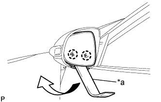
Text in Illustration *a Moulding Remover Using a moulding remover, disengage the 2 claws at the lower part of the outer mirror as shown in the illustration.
-
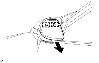
Disengage the 2 guides as shown in the illustration.
-
Disconnect the 2 connectors and remove the outer mirror.
-
-
REMOVE OUTER MIRROR (w/ Memory)
-
Text in Illustration *a Protective Tape Apply protective tape to the area shown in the illustration.
-
Push the upper part of the mirror surface and tilt it.
-
Using a moulding remover, disengage the 2 claws at the lower part of the outer mirror as shown in the illustration.
-
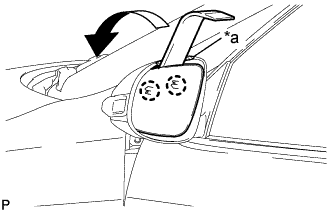
Text in Illustration *a Protective Tape Apply protective tape to the area shown in the illustration.
-
Push the lower part of the mirror surface and tilt it.
-
Using a moulding remover, disengage the 2 claws at the upper part of the outer mirror as shown in the illustration.
-
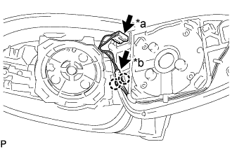
*a Mirror Heater Connector *b Blind Spot Monitor Indicator Connector Disconnect the mirror heater connector.
-
Disengage the 2 claws.
-
Using a screwdriver, release the tabs of the blind spot monitor indicator connector to disconnect the connector and remove the outer mirror.
Note
-
Do not bend the tabs excessively to prevent them from being damaged.
-
If the tabs are damaged, replace the outer mirror with a new one.
-
-
-
REMOVE OUTER MIRROR COVER (w/o Memory)
-
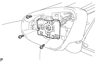
Remove the 3 screws.
-
Disengage the clamp.
-
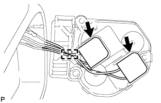
Disconnect the 2 connectors and remove the mirror actuator.
-
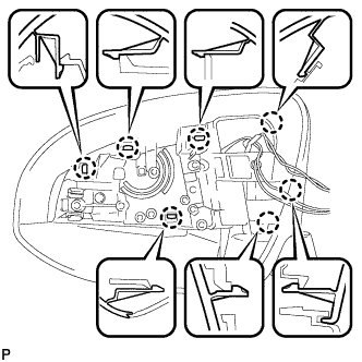
Disengage the 7 claws and remove the outer mirror cover.
-
-
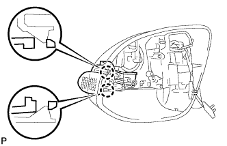
REMOVE OUTER MIRROR COVER (w/ Memory)
-
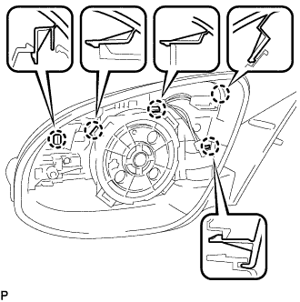
Disengage the 5 claws.
-
Disengage the 2 claws to remove the outer mirror cover as shown in the illustration.
Tech Tips
When removing the outer mirror cover, pull the outer mirror cover horizontally along the lower part of the outer rear view mirror assembly.
-
-
REMOVE SIDE TURN SIGNAL LIGHT ASSEMBLY
-
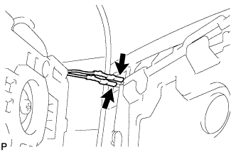
Disengage the 2 claws.
-
Disconnect the connector and remove the side turn signal light assembly.
-