HAZARD WARNING SWITCH INSTALLATION

-
INSTALL HEATER CONTROL SWITCH BOARD
Note
When resassembling the air conditioning control assembly, eliminate static electricity by touching the vehicle body to prevent the components from being damaged.
-
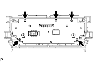
Install the heater control base sub-assembly with the 5 screws.
-
-
INSTALL HEATER CONTROL HOUSING SUB-ASSEMBLY
-
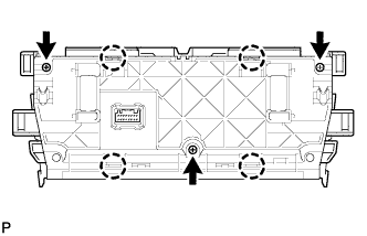
Engage the 4 claws.
-
Install the heater control housing sub-assembly to the heater control retainer RH with the 3 screws.
-
-
INSTALL AIR CONDITIONING PANEL SUB-ASSEMBLY
-
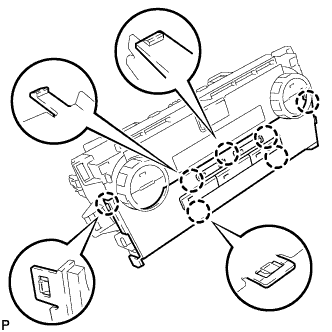
Engage the 7 claws.
-
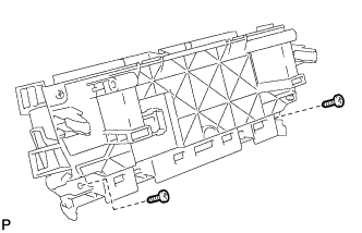
Install the air conditioner panel sub-assembly with the 2 screws.
-
-
INSTALL AIR CONDITIONING CONTROL ASSEMBLY (HAZARD SWITCH)
-
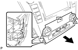
Engage the guide and 4 clips to install the air conditioning control assembly as shown in the illustration.
-
-
INSTALL NO. 1 RADIO BRACKET (w/o Navigation System)
-
Install the No. 1 radio bracket with the 5 screws.
-
-
INSTALL NO. 2 RADIO BRACKET (w/o Navigation System)
-
Install the No. 2 radio bracket with the 5 screws.
-
-
INSTALL NO. 1 RADIO RECEIVER BRACKET (w/ Navigation System)
-
Install the No. 1 radio receiver bracket with the 5 screws.
-
-
INSTALL NO. 2 RADIO RECEIVER BRACKET (w/ Navigation System)
-
Install the No. 2 radio receiver bracket with the 5 screws.
-
-
INSTALL RADIO RECEIVER ASSEMBLY WITH AIR CONDITIONING CONTROL ASSEMBLY (w/o Navigation System)
-
Connect each connector.
-
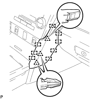
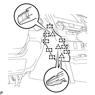
Engage the 6 clips to the vehicle body to temporarily install the radio receiver assembly with air conditioning control assembly.
-
Install the radio receiver assembly with air conditioning control assembly with the 4 bolts.
-
-
INSTALL NAVIGATION RECEIVER ASSEMBLY WITH AIR CONDITIONING CONTROL ASSEMBLY (w/ Navigation System)
-
Connect each connector.
-
Engage the 6 clips to the vehicle body to temporarily install the navigation receiver assembly with air conditioning control assembly.
-
Install the navigation receiver assembly with air conditioning control assembly with the 4 bolts.
-
-
INSTALL FRONT CONSOLE UPPER PANEL GARNISH
-
for Blank Type:
-

Engage the 2 claws to install the front console upper panel garnish as shown in the illustration.
-
-
for 3 Switch Hole Type:
-
Connect each connector.
-
Engage the 2 claws to install the front console upper panel garnish as shown in the illustration.
-
-
-
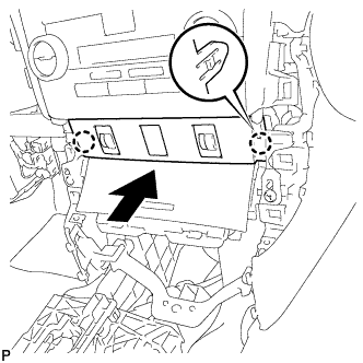
INSTALL NO. 2 INSTRUMENT PANEL REGISTER ASSEMBLY
-
Connect the connector.
-
Engage the 4 clips to install the No. 2 instrument panel register assembly.
Note
When installing the No. 2 instrument panel register assembly, check that the wire harness is not caught between the No. 2 instrument panel register assembly and duct.
-
-
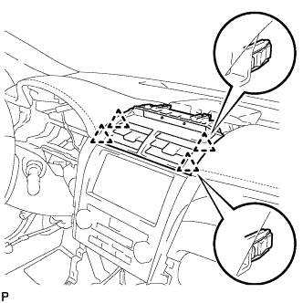
INSTALL CENTER INSTRUMENT CLUSTER FINISH PANEL SUB-ASSEMBLY
-
Engage the 7 clips and 2 guides to install the center instrument cluster finish panel sub-assembly.
-
-
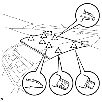
INSTALL FRONT PANEL GARNISH RH
-
Engage the 3 clips and 8 guides to install the front panel garnish RH.
-
-
INSTALL FRONT PANEL GARNISH LH
-
Engage the 3 clips and 8 guides to install the front panel garnish LH.
-
-
CONNECT CABLE TO NEGATIVE BATTERY TERMINAL (w/ Navigation System)
Note
When disconnecting the cable, some systems need to be initialized after the cable is reconnected Click here.