HEADLIGHT ASSEMBLY REASSEMBLY

-
INSTALL GROMMET
-
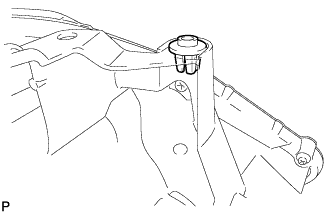
Install the grommet.
-
-
INSTALL HEADLIGHT LEVELING MOTOR BASE PACKING
-
Install a new headlight leveling motor base packing.
-
-
INSTALL HEADLIGHT LEVELING MOTOR (w/o AFS)
-
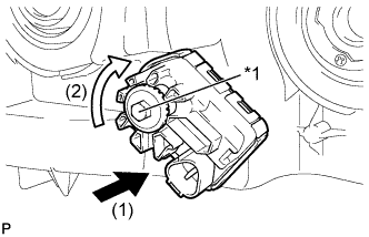
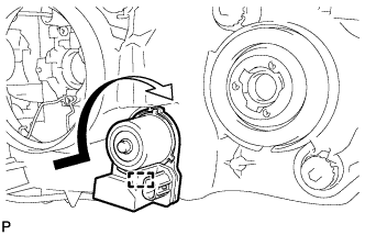
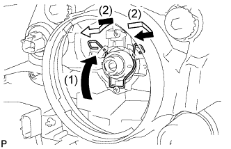
Text in Illustration *1 Aiming Screw Insert the headlight leveling motor in the direction indicated by the arrow (1) shown in the illustration.
-
Turn the aiming screw of the headlight leveling motor in the direction indicated by the arrow (2) shown in the illustration to engage the shaft.
Tech Tips
Turn the aiming screw the same number of times as it was turned during removal.
-
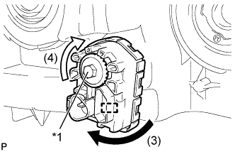
Text in Illustration *1 Aiming Screw Turn the headlight leveling motor in the direction indicated by the arrow (3) shown in the illustration and engage the pin to install the headlight leveling motor to the headlight unit.
Tech Tips
When installing the headlight leveling motor of the headlight assembly RH, turn the headlight leveling motor in the opposite direction indicated by the arrow (3) shown in the illustration.
-
Turn the aiming screw of the headlight leveling motor in the direction indicated by the arrow (4) shown in the illustration to install it.
Tech Tips
Turn the aiming screw the same number of times as it was turned during removal.
-
-
INSTALL HEADLIGHT LEVELING MOTOR (w/ AFS)
-
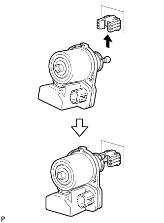
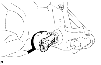
Engage the tip of the headlight leveling motor with the reflector as shown in the illustration.
-
Turn the headlight leveling motor in the direction indicated by the arrow shown in the illustration and engage the pin to install the headlight leveling motor to the headlight unit.
Tech Tips
For the headlight leveling motor RH, rotate it symmetrical to the directional arrow shown in the illustration.
-
-
INSTALL CLEARANCE LIGHT BULB
-
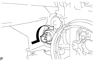
Install the clearance light bulb to the clearance light socket.
-
Turn the clearance light socket with the clearance light bulb in the direction indicated by the arrow shown in the illustration and install them as a unit.
-
-
INSTALL FRONT TURN SIGNAL LIGHT BULB
-
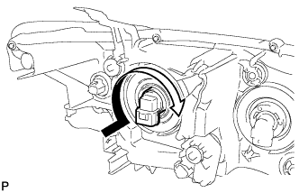
Install the front turn signal light bulb to the front turn signal light socket.
-
Turn the front turn signal light socket with the front turn signal light bulb in the direction indicated by the arrow shown in the illustration and install them as a unit.
-
-
INSTALL HEADLIGHT SOCKET COVER
-
for Halogen Headlight:
-
Install the 2 headlight socket covers to the headlight unit.
-
-
for HID Headlight:
-
Install the headlight socket cover to the headlight unit.
-
-
-
INSTALL NO. 2 HEADLIGHT BULB (for Halogen Headlight)
-
Turn the No. 2 headlight bulb in the direction indicated by the arrow shown in the illustration to install it.
Note
Do not touch the bulb glass.
-
-
INSTALL DISCHARGE HEADLIGHT BULB (for HID Headlight)
-
Set the discharge headlight bulb to the headlight unit.
Note
Do not touch the bulb glass.
-
Lock the set spring to install the discharge headlight bulb as shown in the illustration.
-
-
INSTALL HEADLIGHT LIGHT CONTROL ECU SUB-ASSEMBLY (for HID Headlight)
-
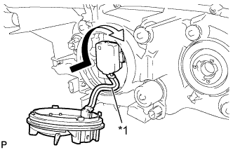
Text in Illustration *1 Red Line Turn the socket of the headlight light control ECU sub-assembly in the direction indicated by the arrow shown in the illustration to connect it.
Note
-
Check that the O-ring is installed on the headlight light control ECU sub-assembly.
-
Check that the O-ring is not damaged or contaminated with foreign matter. If there is any damage, replace the O-ring with a new one.
-
Do not pull the headlight light control ECU sub-assembly with the socket connected.
-
-
Check that the red line on the output harness is not twisted and store the harness in the headlight assembly securely so that the output harness is not pinched.
-
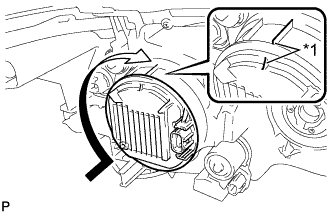
Text in Illustration *1 Lock Mark Turn the headlight light control ECU sub-assembly in the direction indicated by the arrow shown in the illustration until the lock marks are aligned to install it.
Note
-
To prevent incomplete installation, make sure to fully push in and turn the headlight light control ECU sub-assembly until the lock marks are aligned.
-
Do not apply excessive force using a tool.
-
-
-
INSTALL NO. 1 HEADLIGHT BULB
-
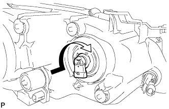
Turn the No. 1 headlight bulb in the direction indicated by the arrow shown in the illustration to install it.
Note
Do not touch the bulb glass.
-