METER / GAUGE SYSTEM SYSTEM DESCRIPTION

-
OUTLINE OF COMBINATION METER ASSEMBLY
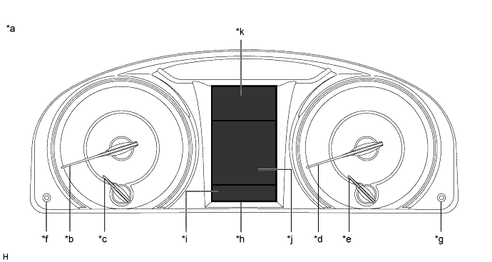
Text in Illustration *a Indication Example *b Tachometer *c Engine Coolant Temperature Receiver Gauge *d Speedometer *e Fuel Receiver Gauge *f Light Control Switch Knob *g ODO/TRIP Switch Knob *h Multi-information Display *i Display Area A *j Display Area B *k Display Area C - - -
INPUT AND OUTPUT SIGNALS OF COMBINATION METER ASSEMBLY
-
Meter or Gauge
Item Condition Input/Output Communication line Signal Component Speedometer Gauge Input CAN Vehicle speed (SP1) signal Brake actuator assembly (Skid control ECU) - Direct line Vehicle speed pulse input signal Output CAN Vehicle speed signal (meter to other) Related ECUs Speed tolerance A signal Speed tolerance B signal Direct line Vehicle speed pulse output signal Related ECUs Tachometer Gauge Input CAN Engine RPM data signal ECM Fuel receiver gauge Gauge Input CAN Starter signal ECM Shift position P signal Shift position N signal Vehicle speed (SP1) signal Brake actuator assembly (Skid control ECU) Parking brake switch signal Main body ECU (Multiplex network body ECU) Direct line Fuel level signal Fuel sender gauge assembly Output CAN Fuel gauge state signal Navigation receiver assembly* Fuel gauge indication signal Fuel level in main tank signal ECM Engine coolant temperature receiver gauge Gauge Input CAN Engine coolant temperature signal ECM
-
*: for Navigation Receiver Type
-
-
Warning or Indicator
Item Condition Input/Output Communication line Signal Component Master warning light Comes on/Blinks Input CAN/Direct line Each warning signal Related ECUs Brake warning light Comes on Input CAN Brake warning light control flag signal Brake actuator assembly (Skid control ECU) Parking brake switch signal Main body ECU (Multiplex network body ECU) Direct line Brake fluid level warning switch signal Brake master cylinder reservoir sub-assembly (Brake fluid level warning switch) Driver seat belt warning light Comes on/Blinks Input CAN Driver seat belt buckle switch signal Main body ECU (Multiplex network body ECU) Shift position P signal ECM Parking brake switch signal Main body ECU (Multiplex network body ECU) SRS warning light Comes on Input CAN Airbag warning light control request signal Airbag sensor assembly Test mode signal ECM EPS warning light Comes on/Blinks Input CAN Demand signal to meter Power steering ECU assembly MIL (Check engine warning light) Comes on/Blinks Input Direct line MIL (Check engine warning light) request signal ECM Slip indicator light Comes on/Blinks Input CAN Slip indicator signal Brake actuator assembly (Skid control ECU) VSC OFF indicator light Comes on Input CAN VSC OFF light signal Brake actuator assembly (Skid control ECU) ABS warning light Comes on/Blinks Input CAN ABS warning light control flag signal Brake actuator assembly (Skid control ECU) Fuel level warning light Comes on Input Direct line Fuel level signal Fuel sender gauge assembly Rear fog indicator light*1 Comes on Input CAN Rear fog light request signal Main body ECU (Multiplex network body ECU) AFS OFF indicator light*2 Comes on/Blinks Input CAN AFS OFF indicator request signal Main body ECU (Multiplex network body ECU) Automatic high beam indicator light*3 Comes on Input CAN Smart beam indicator signal Main body ECU (Multiplex network body ECU) High beam indicator light Comes on Input CAN High beam headlight request signal Main body ECU (Multiplex network body ECU) Front fog indicator light Comes on Input CAN Front fog light request signal Main body ECU (Multiplex network body ECU) Tail indicator light Comes on Input CAN Taillight request signal Main body ECU (Multiplex network body ECU) Turn indicator light Blinks Input CAN Flasher request signal Main body ECU (Multiplex network body ECU) Direct line LH turn signal switch signal Headlight dimmer switch assembly RH turn signal switch signal Turn signal switch position signal Hazard warning switch signal Air conditioning control assembly (Hazard warning signal switch) - Output CAN Turn signal switch state signal Related ECUs Hazard switch state signal Related ECUs Direct line LH turn signal switch signal Each turn signal light RH turn signal switch signal Hazard warning switch signal Eco driving indicator light Comes on Input CAN Ecology light indicator signal ECM
-
*1: w/ Rear Fog Light
-
*2: w/ AFS (Adaptive Front-lighting System)
-
*3: w/ Automatic High Beam System
-
-
Multi-information Display
Item Condition Input/Output Communication line Signal Component Display Area Opening Displayed - - - - ALL Odometer Displayed Input CAN Vehicle speed pulse signal integrated value signal Brake actuator assembly (Skid control ECU) A Vehicle speed (SP1) signal - ODO/TRIP change switch signal ODO/TRIP switch knob (Combination meter assembly) - Output CAN Odometer unit signal Related ECUs Odometer signal TRIP A/TRIP B meter Displayed Input CAN Vehicle speed pulse signal integrated value signal Brake actuator assembly (Skid control ECU) A Vehicle speed (SP1) signal - ODO/TRIP change switch signal ODO/TRIP switch knob (Combination meter assembly) Current fuel consumption Displayed Input CAN Vehicle speed (SP1) signal Brake actuator assembly (Skid control ECU) B Vehicle speed pulse signal integrated value signal Fuel consumption signal ECM Engine RPM data signal - Output CAN Drive monitor unit signal 0
-
Navigation receiver assembly*1
-
Radio and display receiver assembly*9
Drive monitor display signal (Current fuel consumption) Average fuel consumption (After reset) Displayed Input CAN Vehicle speed (SP1) signal Brake actuator assembly (Skid control ECU) B Vehicle speed pulse signal integrated value signal Engine RPM data signal ECM Fuel consumption signal Total average fuel consumption reset request signal
-
Navigation receiver assembly*1
-
Radio and display receiver assembly*9
Direct line Reset signal Steering pad switch assembly - Output CAN Drive monitor unit signal 6
-
Navigation receiver assembly*1
-
Radio and display receiver assembly*9
Drive monitor display signal (Total average fuel consumption) Average fuel consumption (After start) Displayed Input CAN Engine RPM data signal ECM B Fuel consumption signal Vehicle speed (SP1) signal Brake actuator assembly (Skid control ECU) Vehicle speed pulse signal integrated value signal Average speed (After reset) Displayed Input CAN Engine RPM data signal ECM B Vehicle speed (SP1) signal Brake actuator assembly (Skid control ECU) Vehicle speed pulse signal integrated value signal Direct line Reset signal Steering pad switch assembly Average speed (After start) Displayed Input CAN Engine RPM data signal ECM B Vehicle speed (SP1) signal Brake actuator assembly (Skid control ECU) Vehicle speed pulse signal integrated value signal - Output CAN Drive monitor unit signal 1
-
Navigation receiver assembly*1
-
Radio and display receiver assembly*9
Drive monitor display signal (After starting average speed) Elapsed time (After reset) Displayed Input CAN Engine RPM data signal ECM B Direct line Reset signal Steering pad switch assembly Elapsed time (After start) Displayed Input CAN Engine RPM data signal ECM B - Output CAN Drive monitor display signal (After starting driving time)
-
Navigation receiver assembly*1
-
Radio and display receiver assembly*9
Drivable distance Displayed Input CAN Engine RPM data signal ECM B Fuel consumption signal Vehicle speed pulse signal integrated value signal Brake actuator assembly (Skid control ECU) Direct line Fuel level signal Fuel sender gauge assembly - Output CAN Drive monitor unit signal 4
-
Navigation receiver assembly*1
-
Radio and display receiver assembly*9
Drive monitor display signal (Drivable distance) Driving distance (After reset) Displayed Input CAN Engine RPM data signal ECM B Vehicle speed (SP1) signal Brake actuator assembly (Skid control ECU) Vehicle speed pulse signal integrated value signal Driving distance (After start) Displayed Input CAN Engine RPM data signal ECM B Vehicle speed (SP1) signal Brake actuator assembly (Skid control ECU) Vehicle speed pulse signal integrated value signal Other (Blank) Displayed - - - - B Drive information tab Displayed - - - - B Navigation tab*1 Displayed Input CAN/Local bus Navigation signal Navigation receiver assembly B Message tab Displayed - - - - B Setting tab Displayed - - - - B Shift position Displayed Input CAN Shift position P signal ECM C Shift position R signal Shift position N signal Shift position D signal Shift gear signal Mode indicator signal Sports mode enable signal Transmission oil temperature range signal Cruise control SET indicator light*2 Displayed Input CAN Cruise set indicator signal ECM C Cruise control indicator light*2 Displayed Input CAN Cruise main indicator signal ECM C Cruise control warning signal Outside temperature Displayed Input CAN Ambient temperature display signal Air conditioning amplifier assembly C 0 or 0.5°C below decimal point of ambient temperature display switch signal Icy street warning light Displayed Input CAN Ambient temperature display signal Air conditioning amplifier assembly C 0 or 0.5°C below decimal point of ambient temperature display switch signal Phone (Received call) Displayed Input CAN/Local bus Phone (Received call) signal Navigation receiver assembly*1 B Radio and display receiver assembly*9 Turn-by-turn Navigation*1 Displayed Input CAN/Local bus Turn-by-turn signal Navigation receiver assembly B Each door open Displayed Input CAN Driver door open display signal Certification ECU (Smart Key ECU Assembly)*4 B Front passenger door open display signal Rear right door open display signal Rear left door open display signal Driver door courtesy switch signal Main body ECU (Multiplex network body ECU) Front passenger door courtesy switch signal Rear right door courtesy switch signal Rear left door courtesy switch signal Luggage courtesy switch signal Hood courtesy switch signal Vehicle speed (SP1) signal Brake actuator assembly (Skid control ECU) Clearance sonar detection (image display)*3 Displayed Input CAN Cluster indicator turn ON request signal Clearance warning ECU assembly B Front center area information signal Front left area information signal Rear center area information signal Rear left area information signal Rear right area information signal Sensor diag request signal Check Park Sonar System*3 Displayed Input CAN Cluster indicator turn ON request signal Clearance warning ECU assembly B Sensor diag request signal Clean Park Sonar*3 Displayed Input CAN Cluster indicator turn ON request signal Clearance warning ECU assembly B Sensor diag request signal Auto Power OFF to Conserve Battery*4 Displayed Input CAN Message request for push start signal Certification ECU (Smart Key ECU assembly) B Shift to P position when parked*4 Displayed Input CAN Smart system warning 2 signal Certification ECU (Smart key ECU assembly) B Message request for push start signal Release Parking Brake Displayed Input CAN Parking brake switch signal Main body ECU (Multiplex network body ECU) B Vehicle speed (SP1) signal Brake actuator assembly (Skid control ECU) Key not detected*4 Displayed Input CAN Smart system warning 1 signal Certification ECU (Smart key ECU assembly) B Charging System Malfunction See Owner's Manual Displayed Input CAN Charge indicator signal ECM B Direct line Charge L terminal signal Generator assembly Check Entry & Start System*4 Displayed Input CAN Smart system warning 1 signal Certification ECU (Smart key ECU assembly) B BSM not available*5 Displayed Input CAN BSD module status signal Blind spot monitor sensor RH B Check Cruise Control System*2 Displayed Input CAN Cruise control warning signal ECM B Check BSM System*5 Displayed Input CAN BSD module status signal Blind spot monitor sensor RH B Engine Oil Pressure Low Displayed Input CAN Engine RPM data signal ECM B Engine oil pressure warning light demand signal Direct line Engine oil pressure signal Engine oil pressure switch assembly Turn Power OFF*4 Displayed Input CAN Smart system warning 2 signal Certification ECU (Smart key ECU assembly) B Message request for push start signal Key detected in vehicle*4 Displayed Input CAN Smart system warning 3 signal Certification ECU (Smart key ECU assembly) B Moon Roof opened*6 Displayed Input CAN Sliding roof open warning request signal Main body ECU (Multiplex network body ECU) B Depress brake pedal, touch engine switch with key*4 Displayed Input CAN Smart system warning 1 signal Certification ECU (Smart key ECU assembly) B Depress brake pedal and push engine switch to start*4 Displayed Input CAN Smart system warning 3 signal Certification ECU (Smart key ECU assembly) B Message request for push start signal Shift to P position to start*4 Displayed Input CAN Message request for push start signal Certification ECU (Smart key ECU assembly) B Steering Lock active*4 Displayed Input CAN Smart system warning 1 signal Certification ECU (Smart key ECU assembly) B Message request for push start signal Key Battery Low*4 Displayed Input CAN Smart system warning 1 signal Certification ECU (Smart key ECU assembly) B Check Headlight System*7, *8 Displayed Input Direct line Headlight leveling warning signal Headlight leveling ECU assembly*7 B CAN Smart beam indicator signal Main body ECU (Multiplex network body ECU)*8 Washer Fluid Low Displayed Input Direct line Washer fluid level signal Level warning switch assembly B Fuel Low Displayed Input Direct line Fuel level signal Fuel sender gauge assembly B TRC OFF Displayed Input CAN Traction off indicator light signal Brake actuator assembly (Skid control ECU) B Starter signal ECM Power ON*4 Displayed Input CAN Smart system warning 1 signal Certification ECU (Smart key ECU assembly) B Depress brake pedal and push engine switch to start*4 Displayed Input CAN Smart system warning 1 signal Certification ECU (Smart key ECU assembly) B
-
*1: for Navigation Receiver Type
-
*2: w/ Cruise Control System
-
*3: w/ Toyota Parking Assist-sensor System
-
*4: w/ Smart Entry and Start System
-
*5: w/ Blind Spot Monitor System
-
*6: w/ Sliding Roof System
-
*7: w/ Automatic Headlight Beam Level Control System
-
*8: w/ Automatic High Beam System
-
*9: for Radio and Display Type
-
-
Buzzer
Item Condition Input/Output Communication line Signal Component Seat belt warning buzzer Sounds intermittently Input CAN Driver seat buckle switch signal Main body ECU (Multiplex network body ECU) Shift position R signal ECM EPS warning buzzer Sounds once Input CAN Demand buzzer to meter signal Power steering ECU assembly Smart key warning buzzer*1 Sounds intermittently Input CAN Meter buzzer intermittence request signal Certification ECU (Smart key ECU assembly) Sounds intermittently (Maximum 9 times) Input CAN Meter buzzer intermittence request (0.7 sec. cycle) signal Certification ECU (Smart key ECU assembly) Sounds continuously Input CAN Meter buzzer continuation request signal Certification ECU (Smart key ECU assembly) Sounds once Input CAN Meter buzzer single-shot request signal Certification ECU (Smart key ECU assembly) Key reminder buzzer*2 Sounds intermittently Input CAN Key switch signal Main body ECU (Multiplex network body ECU) Driver door courtesy switch signal Multi-information display warning buzzer Sounds once Input CAN Multi-information display warning signal Related ECUs Direct line Immobiliser key identification completion buzzer*1 Sounds once Input CAN Immobiliser key identification completion signal Certification ECU (Smart key ECU assembly) Driving with parking brake unreleased warning buzzer Sounds intermittently Input CAN Parking brake switch signal Main body ECU (Multiplex network body ECU) Vehicle speed (SP1) signal Brake actuator assembly (Skid control ECU) Driving with door open warning buzzer Sounds intermittently Input CAN Driver door courtesy switch signal Main body ECU (Multiplex network body ECU) Front passenger door courtesy switch signal Rear right door courtesy switch signal Rear left door courtesy switch signal Luggage courtesy switch signal Hood courtesy switch signal Vehicle speed (SP1) signal Brake actuator assembly (Skid control ECU) Sports shift reject buzzer Sounds twice Input CAN Reject buzzer signal ECM Sliding roof warning buzzer*3 Sounds once Input CAN Sliding roof open warning request signal Main body ECU (Multiplex network body ECU) Turn signal flasher buzzer Sounds intermittently Input Direct line LH turn signal switch signal Headlight dimmer switch assembly RH turn signal switch signal Hazard warning switch signal Air conditioning control assembly (Hazard warning signal switch)
-
*1: w/ Smart Entry and Start System
-
*2: w/o Smart Entry and Start System
-
*3: w/ Sliding Roof System
-
-
Others
Item Condition Input/Output Communication line Signal Component Meter illumination Illumination level Input CAN Auto dimmer signal Main body ECU (Multiplex network body ECU) Taillight request signal - Illumination level signal Light control rheostat switch knob (Combination meter assembly) - Output Direct line Illumination level output signal Related ECUs
-
-
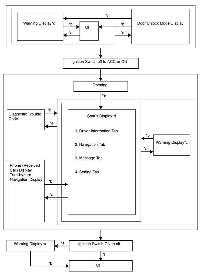
MULTI-INFORMATION DISPLAY FLOW CHART
-
Multi-information display flow chart
-
-
DESCRIPTION OF WARNING DISPLAYS
Priority System Name/(Vehicle Function) Master Warning Light
○: Comes on
●: Blinks
Buzzer
(*1)
Display Level 1 (Each door warning (vehicle being driven)) ● * Each door open (vehicle being driven) Caution (Each door warning (vehicle stopped)) - - Each door open (vehicle stopped) Caution Toyota parking assist-sensor system - - Clearance sonar detection (image display) Caution ○ - Check Park Sonar System Caution ○ - Clean Park Sonar Caution 2 Smart entry and start system - * Auto Power OFF to Conserve Battery Caution 3 Smart entry and start system ● */○ Shift to P position when parked Caution 4 (Parking brake) ● * Release Parking Brake Caution Smart entry and start system ● * Key not detected Caution 5 Charging system - - Charging System Malfunction See Owner's Manual Caution Smart entry and start system ● * Check Entry & Start System Caution Blind spot monitor system ○ ○ BSM not available Caution Cruise control system ○ ○ Check Cruise Control System Caution Blind spot monitor system ○ ○ Check BSM System Caution (Engine oil pressure switch assembly) ○ ○ Engine Oil Pressure Low Caution 6 Smart entry and start system ● */○ Turn Power OFF Caution ● ○ Key detected in vehicle Caution Sliding roof system ● ○ Moon Roof opened Caution Smart entry and start system ● * Depress brake pedal, touch engine switch with key Caution ● * Depress brake pedal and push engine switch to start Caution ● ○ Shift to P position to start Caution 7 Steering lock system ● * Steering Lock active Caution 8 Smart entry and start system ○ * Key Battery Low Caution Automatic headlight beam level control system or Automatic high beam system ○ ○ Check Headlight System Caution 9 (Level warning switch assembly) - - Washer Fluid Low Advisory (Fuel sender gauge assembly) - - Fuel Low Advisory Vehicle stability control system - - TRC OFF Caution Smart entry and start system - - Power ON Caution - - Depress brake pedal and push engine switch to start Caution
-
*: An exclusive buzzer sounds depending on condition
-
*1: Buzzers that are linked with the master warning light
-