LIGHTING SYSTEM Footwell Light Circuit
DESCRIPTION
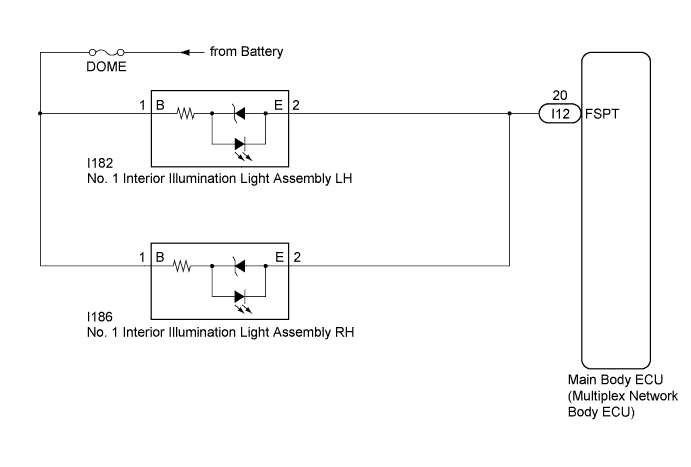
The main body ECU (multiplex network body ECU) controls the footwell lights.
WIRING DIAGRAM
INSPECTION PROCEDURE
Note
Inspect the fuses for circuits related to this system before performing the following inspection procedure.
PROCEDURE
-
PERFORM ACTIVE TEST USING INTELLIGENT TESTER
-
Connect the intelligent tester to the DLC3.
-
Turn the ignition switch to ON.
-
Turn the intelligent tester on.
-
Enter the following menus: Body Electrical / Main Body / Active Test.
-
Perform the Active Test according to the display on the intelligent tester.
Main Body Tester Display Test Part Control Range Diagnostic Note Fr Foot Light Footwell lights ON/OFF Turn off the ignition switch just before performing the Active Test. OK Footwell lights come on.
NG 
CHECK HARNESS AND CONNECTOR (DOME FUSE - NO. 1 INTERIOR ILLUMINATION LIGHT ASSEMBLY) Click here
OK 
PROCEED TO NEXT SUSPECTED AREA SHOWN IN PROBLEM SYMPTOMS TABLE Click here
-
-
CHECK HARNESS AND CONNECTOR (DOME FUSE - NO. 1 INTERIOR ILLUMINATION LIGHT ASSEMBLY)
-
Disconnect the I182 No. 1 interior illumination light assembly LH connector.
-
Disconnect the I186 No. 1 interior illumination light assembly RH connector.
-
Measure the voltage according to the value(s) in the table below.
Standard Voltage Tester Connection Condition Specified Condition I182-1 (B) - Body ground Always 11 to 14 V I186-1 (B) - Body ground Always 11 to 14 V
NG 
REPAIR OR REPLACE HARNESS OR CONNECTOR
OK 
-
-
CHECK HARNESS AND CONNECTOR (NO. 1 INTERIOR ILLUMINATION LIGHT ASSEMBLY - MAIN BODY ECU (MULTIPLEX NETWORK BODY ECU))
-
Disconnect the I12 main body ECU (multiplex network body ECU) connector.
-
Measure the resistance according to the value(s) in the table below.
Standard Resistance Tester Connection Condition Specified Condition I182-2 (E) - I12-20 (FSPT) Always Below 1 Ω I186-2 (E) - I12-20 (FSPT) Always Below 1 Ω I182-2 (E) - Body ground Always 10 kΩ or higher I186-2 (E) - Body ground Always 10 kΩ or higher
NG
REPAIR OR REPLACE HARNESS OR CONNECTOR
OK
REPLACE MAIN BODY ECU (MULTIPLEX NETWORK BODY ECU) Click here
-