BLOCKING SYSTEM Engine does not Start
DESCRIPTION
If the engine does not start and no DTCs are output, the following conditions may apply:
-
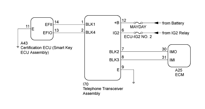
There is a short circuit between the telephone transceiver assembly and the certification ECU (smart key ECU assembly).
-
The blocking system is set.
WIRING DIAGRAM
INSPECTION PROCEDURE
Note
-
Before troubleshooting this symptom, make sure no engine immobiliser system DTCs or blocking system DTCs are present. If present, troubleshoot the engine immobiliser system DTCs or blocking system DTCs first.
-
When replacing the telephone transceiver assembly and certification ECU (smart key ECU assembly), refer to the Service Bulletin.
-
When the telephone transceiver assembly is replaced, it is necessary to set the contract mode.
-
Inspect the fuses for circuits related to this system before performing the following inspection procedure.
PROCEDURE
-
CHECK BLOCKING SYSTEM (SETTING)
-
Check the blocking system setting.
Tech Tips
Check with the customer's contracted service provider to determine whether the blocking system is set.
Result Result Proceed to Blocking system is unset. A Blocking system is set. B
B 
UNSET BLOCKING SYSTEM
A 
-
-
CHECK HARNESS AND CONNECTOR (TELEPHONE TRANSCEIVER ASSEMBLY - CERTIFICATION ECU (SMART KEY ECU ASSEMBLY))
-
Disconnect the I70 telephone transceiver assembly connector.
-
Disconnect the A43 certification ECU (smart key ECU assembly) connector.
-
Measure the resistance according to the value(s) in the table below.
Standard Resistance Tester Connection Condition Specified Condition I70-1 (BLK1) - A43-14 (EFII) Always 10 kΩ or higher I70-2 (BLK4) - A43-13 (EFIO) Always 10 kΩ or higher
NG
REPAIR OR REPLACE HARNESS OR CONNECTOR
OK
-
-
CHECK CERTIFICATION ECU (SMART KEY ECU ASSEMBLY) (OUTPUT)
-
Reconnect the I70 telephone transceiver assembly connector.
-
Reconnect the A43 certification ECU (smart key ECU assembly) connector.
-
Using an oscilloscope, check the waveform.
Note
The waveform shown in the illustration is an example for reference only. Noise, chattering, etc. are not shown.
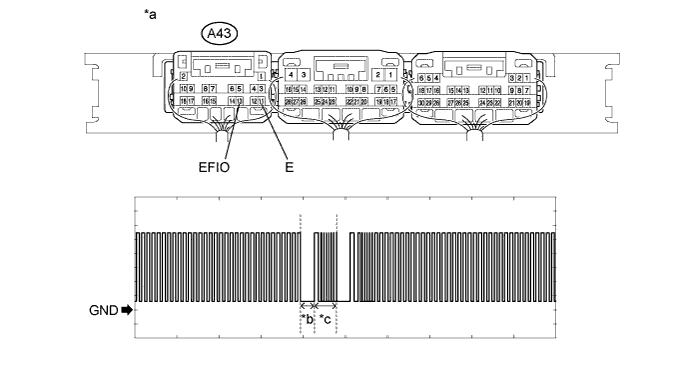
Text in Illustration *a Component with harness connected
(Certification ECU (Smart Key ECU Assembly))
*b Approximately 160 ms *c Approximately 270 ms - - Measurement Condition Item Content Tester Connection A43-13 (EFIO) - A43-11 (E) Tool Setting 2 V/DIV., 500 ms./DIV. Condition Within 3 seconds of engine start or within 3 seconds of engine switch turned on (IG) after battery cable disconnected and reconnected OK The waveform is output normally (refer to illustration). Result Result Proceed to NG (stuck high) A NG (stuck low) B OK C
B
REPLACE TELEPHONE TRANSCEIVER ASSEMBLY
C 
REGISTER ECU COMMUNICATION ID Click here
A
-
-
REPLACE CERTIFICATION ECU (SMART KEY ECU ASSEMBLY)
-
Temporarily replace the certification ECU (smart key ECU assembly) with a new one.
Tech Tips
Refer to the Service Bulletin.
NEXT
-
-
PERFORM REGISTRATION
-
Perform the registration.
Tech Tips
Refer to the Service Bulletin.
NEXT
-
-
CHECK WHETHER ENGINE STARTS
-
Check that the engine starts normally.
OK Engine starts normally.
NG
REPLACE TELEPHONE TRANSCEIVER ASSEMBLY
OK 
END (CERTIFICATION ECU (SMART KEY ECU ASSEMBLY) WAS DEFECTIVE)
-
-
REGISTER ECU COMMUNICATION ID
-
Register the ECU communication ID between the ECM and certification ECU (smart key ECU assembly).
Tech Tips
Refer to the Service Bulletin.
NEXT
-
-
CHECK WHETHER ENGINE STARTS
-
Check that the engine starts normally.
OK Engine starts normally.
NG
REPLACE TELEPHONE TRANSCEIVER ASSEMBLY
OK
END (ECU COMMUNICATION ID WAS NOT REGISTERED CORRECTLY)
-