ENGINE IMMOBILISER SYSTEM (w/ Smart Entry and Start System), Diagnostic DTC:B2799

| DTC Code | DTC Name |
|---|---|
| B2799 | Engine Immobiliser System Malfunction |
DESCRIPTION
-
w/o Wireless Door Lock Buzzer Answer Back Function:
When there are communication malfunctions between the ECM and ID code box (immobiliser code ECU), or when the communication ID codes do not match, the ECM stores this DTC.
-
w/o Wireless Door Lock Buzzer Answer Back Function:
When there are communication malfunctions between the ECM and certification ECU (smart key ECU assembly), or when the communication ID codes do not match, the ECM stores this DTC.
| DTC Code | DTC Detection Condition | Trouble Area | DTC Output Confirmation Operation |
|---|---|---|---|
| B2799 | Either condition is met (1 trip detection logic*4):
|
|
Either condition is met:
|
-
*1: w/o Wireless Door Lock Buzzer Answer Back Function
-
*2: w/ Wireless Door Lock Buzzer Answer Back Function
-
*3: w/ Blocking System
-
*4: Only output while a malfunction is present.
| Vehicle Condition when Malfunction Detected | Fail-safe Operation when Malfunction Detected |
|---|---|
| Engine cannot be started | - |
| DTC Code | Data List and Active Test |
|---|---|
| B2799 | - |
WIRING DIAGRAM
-
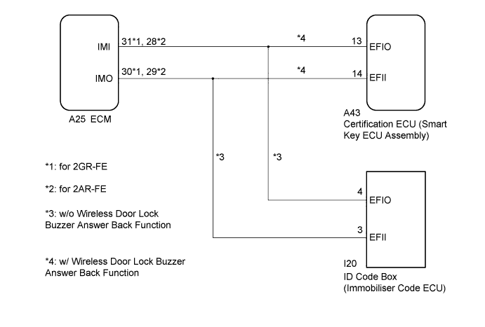
w/o Blocking System
-
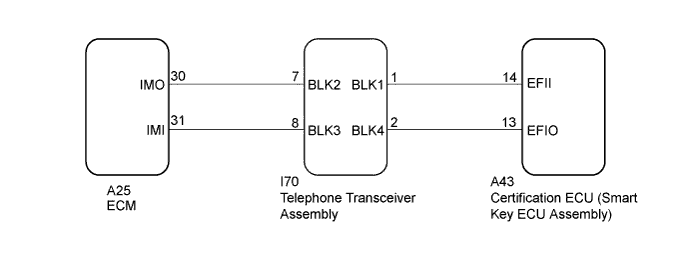
w/ Blocking System
INSPECTION PROCEDURE
Note
-
When replacing the certification ECU (smart key ECU assembly)*1, ID code box (immobiliser code ECU)*2 or telephone transceiver assembly*3, refer to Service Bulletin.
-
After performing repairs, perform the operation that fulfills the DTC output confirmation operation, and then confirm that no DTCs are output again.
-
When the telephone transceiver assembly is replaced, it is necessary to set the contract mode.*
-
*1: w/ Blocking System and Wireless Door Lock Buzzer Answer Back Function
-
*2: w/o Wireless Door Lock Buzzer Answer Back Function
-
*3: w/ Blocking System
Tech Tips
When DTC B2799 and the certification ECU (smart key ECU assembly) DTC are output simultaneously, first perform troubleshooting for the certification ECU (smart key ECU assembly) DTC.
PROCEDURE
-
REGISTER ECU COMMUNICATION ID
-
Register the ECU communication ID.
Tech Tips
Refer to Service Bulletin.
NEXT 
-
-
CLEAR DTC
-
Clear the DTCs Click here.
NEXT
-
-
CHECK FOR DTC
-
Start the engine.
-
Perform "DTC Output Confirmation Operation" procedure.
-
Check for DTCs Click here.
OK DTC B2799 is not output. Result Result Proceed to OK A NG (DTC B2799 is output) (w/ Blocking System) B NG (DTC B2799 is output) (w/o Blocking System and w/ Wireless Door Lock Buzzer Answer Back Function) C NG (DTC B2799 is output) (w/o Blocking System and Wireless Door Lock Buzzer Answer Back Function) D NG (Other DTCs are output) E
B 
CHECK HARNESS AND CONNECTOR (ECM - TELEPHONE TRANSCEIVER ASSEMBLY) Click here
C
CHECK HARNESS AND CONNECTOR (CERTIFICATION ECU (SMART KEY ECU ASSEMBLY) - ECM) Click here
D
REGISTER ECU COMMUNICATION ID Click here
E 
GO TO DIAGNOSTIC TROUBLE CODE CHART Click here
A 
END (COMMUNICATION ID REGISTRATION WAS DEFECTIVE)
-
-
CHECK HARNESS AND CONNECTOR (ECM - TELEPHONE TRANSCEIVER ASSEMBLY)
-
Disconnect the A25 ECM connector.
-
Disconnect the I70 telephone transceiver assembly connector.
-
Measure the resistance according to the value(s) in the table below.
Standard Resistance Tester Connection Condition Specified Condition A25-30 (IMO) - I70-7 (BLK2) Always Below 1 Ω A25-30 (IMO) or I70-7 (BLK2) - Body ground Always 10 kΩ or higher A25-31 (IMI) - I70-8 (BLK3) Always Below 1 Ω A25-31 (IMI) or I70-8 (BLK3) - Body ground Always 10 kΩ or higher
NG
REPAIR OR REPLACE HARNESS OR CONNECTOR
OK
-
-
CHECK HARNESS AND CONNECTOR (TELEPHONE TRANSCEIVER ASSEMBLY - CERTIFICATION ECU (SMART KEY ECU ASSEMBLY)
-
Disconnect the A43 certification ECU (smart key ECU assembly) connector.
-
Measure the resistance according to the value(s) in the table below.
Standard Resistance Tester Connection Condition Specified Condition I70-1 (BLK1) - A43-14 (EFII) Always Below 1 Ω I70-1 (BLK1) or A43-14 (EFII) - Body ground Always 10 kΩ or higher I70-2 (BLK4) - A43-13 (EFIO) Always Below 1 Ω I70-2 (BLK4) or A43-13 (EFIO) - Body ground Always 10 kΩ or higher
NG
REPAIR OR REPLACE HARNESS OR CONNECTOR
OK
-
-
REPLACE TELEPHONE TRANSCEIVER ASSEMBLY
-
Temporarily replace the telephone transceiver assembly with a new or known good one.
Tech Tips
Refer to Service Bulletin.
NEXT
-
-
REGISTER ECU COMMUNICATION ID
-
Register the ECU communication ID.
Tech Tips
Refer to Service Bulletin.
NEXT
-
-
CLEAR DTC
-
Clear the DTCs Click here.
NEXT
-
-
CHECK FOR DTC
-
Perform "DTC Output Confirmation Operation" procedure.
-
Check for DTCs Click here.
OK DTC B2799 is not output.
NG
INSPECT CERTIFICATION ECU (SMART KEY ECU ASSEMBLY) (TERMINAL EFII) Click here
OK
END (TELEPHONE TRANSCEIVER ASSEMBLY WAS DEFECTIVE)
-
-
CHECK HARNESS AND CONNECTOR (CERTIFICATION ECU (SMART KEY ECU ASSEMBLY) - ECM)
-
Disconnect the A43 certification ECU (smart key ECU assembly) connector.
-
Disconnect the A25 ECM connector.
-
Measure the resistance according to the value(s) in the table below.
Standard Resistance Tester Connection Condition Specified Condition A43-14 (EFII) - A25-29 (IMO) Always Below 1 Ω A43-14 (EFII) or A25-29 (IMO) - Body ground Always 10 kΩ or higher A43-13 (EFIO) - A25-28 (IMI) Always Below 1 Ω A43-13 (EFIO) or A25-28 (IMI) - Body ground Always 10 kΩ or higher
NG
REPAIR OR REPLACE HARNESS OR CONNECTOR
OK
-
-
INSPECT CERTIFICATION ECU (SMART KEY ECU ASSEMBLY) (TERMINAL EFII)
-
Using an oscilloscope, check the waveform.
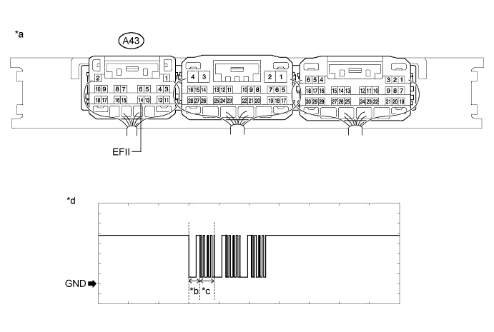
Text in Illustration *a Component with harness connected
(Certification ECU (Smart Key ECU Assembly))
*b Approximately 160 ms *c Approximately 270 ms *d Waveform Measurement Condition Tester Connection Condition Tool Setting Specified Condition A43-14 (EFII) - Body ground Within 3 seconds of engine start or within 3 seconds of engine switch turned on (IG) after battery cable disconnected and reconnected 2 V/DIV., 500 ms./DIV. Pulse generation
(See waveform)
OK The waveform is similar to that shown in the illustration. Result Result Proceed to Normal waveform A Terminal IMO stuck low (2.4 V or less) B Terminal IMO stuck high (12 V), or has abnormal wavelength or shape C
B
INSPECT ECM (IMO TERMINAL VOLTAGE) Click here
C
REPLACE ECM Click here
A
-
-
INSPECT CERTIFICATION ECU (SMART KEY ECU ASSEMBLY) (TERMINAL EFIO)
-
Using an oscilloscope, check the waveform.
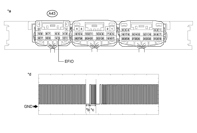
Text in Illustration *a Component with harness connected
(Certification ECU (Smart Key ECU Assembly))
*b Approximately 160 ms *c Approximately 270 ms *d Waveform Measurement Condition Tester Connection Condition Tool Setting Specified Condition A43-13 (EFIO) - Body ground Engine switch on (IG) using registered electrical key transmitter sub-assembly 2 V/DIV., 500 ms./DIV. Pulse generation
(See waveform)
OK The waveform is similar to that shown in the illustration.
NG
REPLACE CERTIFICATION ECU (SMART KEY ECU ASSEMBLY)
OK
-
-
REGISTER ECU COMMUNICATION ID
-
Register the ECU communication ID.
Tech Tips
Refer to Service Bulletin.
NEXT
-
-
CHECK WHETHER ENGINE STARTS
-
Using an electrical key transmitter sub-assembly which is registered to the vehicle, turn the engine switch on (IG).
-
Check that the engine starts 5 seconds after the engine switch was turned on (IG).
OK Engine starts normally.
NG
REPLACE ECM Click here
OK
END (COMMUNICATION ID REGISTRATION WAS DEFECTIVE)
-
-
INSPECT ECM (IMO TERMINAL VOLTAGE)
-
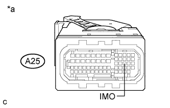
Text in Illustration *a Front view of wire harness connector
(to ECM)
Disconnect the A25 ECM connector.
-
Turn the engine switch on (IG).
-
Measure the voltage according to the value(s) in the table below.
Standard Voltage Tester Connection Condition Specified Condition A25-29 (IMO) - Body ground Engine switch on (IG) using registered electrical key transmitter sub-assembly Terminal IMO stuck low (2.4 V or less) Terminal IMO stuck high (12 V) or abnormal waveform Result Result Proceed to Terminal IMO stuck low (2.4 V or less) A Terminal IMO stuck high (12 V) or abnormal waveform B
B
REPLACE ECM Click here
A
-
-
REPLACE CERTIFICATION ECU (SMART KEY ECU ASSEMBLY)
-
Replace the certification ECU (smart key ECU assembly) with a new one.
Tech Tips
Refer to Service Bulletin.
NEXT
-
-
REGISTER ECU COMMUNICATION ID
-
Register the ECU communication ID.
Tech Tips
Refer to Service Bulletin.
NEXT
-
-
CHECK WHETHER ENGINE STARTS
-
Using an electrical key transmitter sub-assembly which is registered to the vehicle, turn the engine switch on (IG).
-
Check that the engine starts 5 seconds after the engine switch was turned on (IG).
OK Engine starts normally.
NG
REPLACE ECM Click here
OK
END (CERTIFICATION ECU (SMART KEY ECU ASSEMBLY) WAS DEFECTIVE)
-
-
REGISTER ECU COMMUNICATION ID
Register the ECU communication ID.
Tech Tips
Refer to Service Bulletin.
NEXT
-
CLEAR DTC
-
Clear the DTCs Click here.
NEXT
-
-
CHECK FOR DTC
-
Perform "DTC Output Confirmation Operation" procedure.
-
Check for DTCs Click here.
OK DTC B2799 is not output.
NG
CHECK HARNESS AND CONNECTOR (ID CODE BOX (IMMOBILISER CODE ECU) - ECM) Click here
OK
END (COMMUNICATION ID REGISTRATION WAS DEFECTIVE)
-
-
CHECK HARNESS AND CONNECTOR (ID CODE BOX (IMMOBILISER CODE ECU) - ECM)
-
Disconnect the I20 ID code box (immobiliser code ECU) connector.
-
Disconnect the A25 ECM connector.
-
Measure the resistance according to the value(s) in the table below.
Standard Resistance for 2GR-FE Tester Connection Condition Specified Condition I20-3 (EFII) - A25-30 (IMO) Always Below 1 Ω I20-3 (EFII) or A25-30 (IMO) - Body ground Always 10 kΩ or higher I20-4 (EFIO) - A25-31 (IMI) Always Below 1 Ω I20-4 (EFIO) or A25-31 (IMI) - Body ground Always 10 kΩ or higher for 2AR-FE Tester Connection Condition Specified Condition I20-3 (EFII) - A25-29 (IMO) Always Below 1 Ω I20-3 (EFII) or A25-29 (IMO) - Body ground Always 10 kΩ or higher I20-4 (EFIO) - A25-28 (IMI) Always Below 1 Ω I20-4 (EFIO) or A25-28 (IMI) - Body ground Always 10 kΩ or higher
NG
REPAIR OR REPLACE HARNESS OR CONNECTOR
OK
-
-
REPLACE ECM
-
Temporarily replace the ECM with a new one Click here for 2GR-FE , Click here for 2AR-FE).
NEXT
-
-
CLEAR DTC
-
Clear the DTCs Click here.
NEXT
-
-
CHECK FOR DTC
-
Perform "DTC Output Confirmation Operation" procedure.
-
Check for DTCs Click here.
OK DTC B2799 is not output.
NG
REPLACE ID CODE BOX (IMMOBILISER CODE ECU)
OK
END (ECM WAS DEFECTIVE)
-