ENGINE IMMOBILISER SYSTEM (w/ Smart Entry and Start System), Diagnostic DTC:B2784

| DTC Code | DTC Name |
|---|---|
| B2784 | Antenna Coil Open / Short |
DESCRIPTION
When an open or short circuit is detected in the transponder key amplifier coil built into the engine switch, the certification ECU (smart key ECU assembly) stores this DTC. This DTC is also stored as a past DTC.
| DTC Code | DTC Detection Condition | Trouble Area | DTC Output Confirmation Operation |
|---|---|---|---|
| B2784 | The transponder key amplifier coil built into the engine switch is open (see below) or shorted (determined by communication with certification ECU (smart key ECU assembly)) (1 trip detection logic*).
|
|
With the shift lever in P, the key is held near the engine switch and an engine start operation is performed by pressing and holding the engine switch when the key battery is depleted. |
-
*: Only output while a malfunction is present.
| Vehicle Condition when Malfunction Detected | Fail-safe Operation when Malfunction Detected |
|---|---|
| Engine cannot be started when key battery is depleted by holding key near engine switch and pressing and holding engine switch with shift lever in P | - |
| DTC Code | Data List and Active Test |
|---|---|
| B2784 | - |
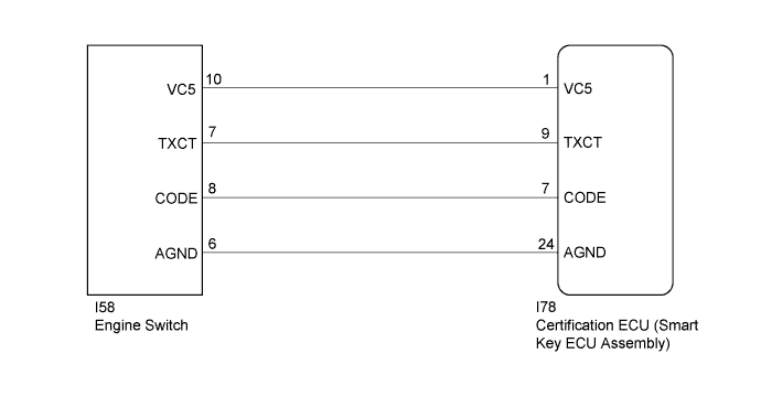
WIRING DIAGRAM
INSPECTION PROCEDURE
Note
-
Before replacing the certification ECU (smart key ECU assembly), refer to the Service Bulletin.
-
After performing repairs, perform the operation that fulfills the DTC output confirmation operation, and then confirm that no DTCs are output again.
PROCEDURE
-
CHECK HARNESS AND CONNECTOR (CERTIFICATION ECU (SMART KEY ECU ASSEMBLY) - ENGINE SWITCH)
-
Disconnect the I78 certification ECU (smart key ECU assembly) connector.
-
Disconnect the I58 engine switch connector.
-
Measure the resistance according to the value(s) in the table below.
Standard Resistance Tester Connection Condition Specified Condition I78-7 (CODE) - I58-8 (CODE) Always Below 1 Ω I78-9 (TXCT) - I58-7 (TXCT) Always Below 1 Ω I78-1 (VC5) - I58-10 (VC5) Always Below 1 Ω I78-24 (AGND) - I58-6 (AGND) Always Below 1 Ω I58-8 (CODE) - Body ground Always 10 kΩ or higher I58-7 (TXCT) - Body ground Always 10 kΩ or higher I58-10 (VC5) - Body ground Always 10 kΩ or higher I58-6 (AGND) - Body ground Always 10 kΩ or higher
NG 
REPAIR OR REPLACE HARNESS OR CONNECTOR
OK 
-
-
REPLACE ENGINE SWITCH
-
Temporarily replace the engine switch with a new or known good one Click here for 2GR-FE, Click here for 2AR-FE).
NEXT
-
-
CLEAR DTC
-
Clear the DTCs Click here.
NEXT
-
-
CHECK DTC OUTPUT
-
Check for DTCs Click here.
Tech Tips
Before checking for DTCs, perform the "DTC Output Confirmation Operation" procedure.
OK DTC B2784 is not output.
NG
REPLACE CERTIFICATION ECU (SMART KEY ECU ASSEMBLY)
OK 
END (ENGINE SWITCH WAS DEFECTIVE)
-