ENGINE IMMOBILISER SYSTEM (w/o Smart Entry and Start System), Diagnostic DTC:B2784

| DTC Code | DTC Name |
|---|---|
| B2784 | Antenna Coil Open / Short |
DESCRIPTION
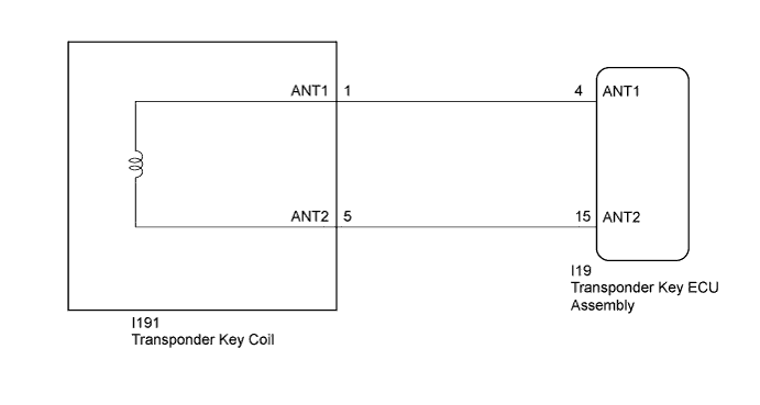
When an open or short circuit is detected in the antenna coil built into the transponder key coil, the transponder key ECU assembly stores this DTC.
| DTC No. | DTC Detection Condition | Trouble Area | DTC Output Confirmation Operation |
|---|---|---|---|
| B2784 | The antenna coil in the transponder key coil is open/shorted. |
|
Insert the door control transmitter assembly into the ignition key cylinder, turn the ignition switch from off to ON and wait at least 20 seconds. |
| Vehicle Condition when Malfunction Detected | Fail-safe Operation when Malfunction Detected |
|---|---|
| Engine cannot be started | - |
| DTC No. | Data List and Active Test |
|---|---|
| B2784 | Antenna Coil Status |
WIRING DIAGRAM
INSPECTION PROCEDURE
Note
-
If the transponder key ECU assembly is replaced, refer to Service Bulletin.
-
After repair, confirm that no DTCs are output by performing "DTC Output Confirmation Operation".
PROCEDURE
-
CLEAR DTC
-
Clear the DTCs Click here.
NEXT 
-
-
CHECK FOR DTC
-
Perform "DTC Output Confirmation Operation" procedure.
-
Check for DTCs Click here.
OK DTC B2784 is not output. Result Result Proceed to B2784 is not output A B2784 is output B
B 
CHECK CONNECTION OF CONNECTOR Click here
A 
USE SIMULATION METHOD TO CHECK Click here
-
-
CHECK CONNECTION OF CONNECTOR
-
Check that the connector is properly connected to the transponder key coil.
NEXT
-
-
CLEAR DTC
-
Clear the DTCs Click here.
NEXT
-
-
CHECK FOR DTC
-
Perform "DTC Output Confirmation Operation" procedure.
-
Check for DTCs. Click here.
OK DTC B2784 is not output. Result Result Proceed to B2784 is not output A B2784 is output B
B
CHECK TRANSPONDER KEY COIL (OUTPUT) Click here
A
END (CONNECTOR WAS NOT CONNECTED PROPERLY)
-
-
CHECK TRANSPONDER KEY COIL (OUTPUT)
-
Using an oscilloscope, check the waveform.
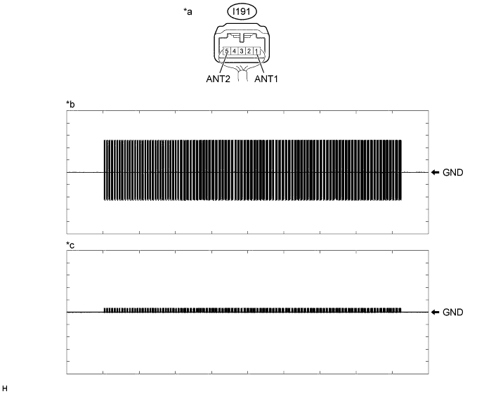
OK Tester Connection Condition Tool Setting Specified Condition I191-1 (ANT1) - Body ground Within 3 seconds of inserting door control transmitter assembly into ignition key cylinder 2 V/DIV., 500 ms./DIV. Pulse generation
(See waveform 1)
I191-5 (ANT2) - Body ground Within 3 seconds of inserting door control transmitter assembly into ignition key cylinder 2 V/DIV., 500 ms./DIV. Pulse generation
(See waveform 2)
OK Waveform is similar to that shown in the illustration. Text in Illustration *a Component with harness connected
(Transponder Key Coil)
*b Waveform 1 *c Waveform 2 - - Result Result Proceed to NG A OK B
B
REPLACE TRANSPONDER KEY ECU ASSEMBLY Click here
A
-
-
CHECK HARNESS AND CONNECTOR (TRANSPONDER KEY ECU ASSEMBLY - TRANSPONDER KEY COIL)
-
Disconnect the I19 transponder key ECU assembly connector.
-
Disconnect the I191 transponder key coil connector.
-
Measure the resistance according to the value(s) in the table below.
Standard Resistance Tester Connection Condition Specified Condition I19-4 (ANT1) - I191-1 (ANT1) Always Below 1 Ω I19-15 (ANT2) - I191-5 (ANT2) Always Below 1 Ω I19-4 (ANT1) or I191-1 (ANT1) - Body ground Always 10 kΩ or higher I19-15 (ANT2) or I191-5 (ANT2) - Body ground Always 10 kΩ or higher
NG 
REPAIR OR REPLACE HARNESS OR CONNECTOR
OK
-
-
REPLACE TRANSPONDER KEY ECU ASSEMBLY
-
Temporarily replace the transponder key ECU assembly with a new one.
Tech Tips
Refer to Service Bulletin.
Note
Key ID code registration is necessary when replacing the transponder key ECU assembly, refer to Service Bulletin.
NEXT
-
-
CLEAR DTC
-
Clear the DTCs Click here.
NEXT
-
-
CHECK FOR DTC
-
Perform "DTC Output Confirmation Operation" procedure.
-
Check for DTCs Click here.
OK DTC B2784 is not output. Result Result Proceed to B2784 is not output A B2784 is output B
B
REPLACE TRANSPONDER KEY COIL Click here
A
END (TRANSPONDER KEY ECU ASSEMBLY WAS DEFECTIVE)
-