PUSH-BUTTON START OPERATION CHECK

-
OPERATION DESCRIPTION
-
Push-button start function:
-
When the key is in a detection area inside the vehicle and the brake pedal is depressed, the engine is started by pressing the engine switch.
-
When the key is in a detection area inside the vehicle and the brake pedal is not depressed, the power source mode is changed by pressing the engine switch. The power source mode changes in the following order every time the engine switch is pressed: off → on (ACC) → on (IG) → off.
-
After getting into the vehicle while carrying the key when the engine switch is off, if the engine switch is pressed while not depressing the brake pedal, the power source mode changes to on (ACC).
-
After getting into the vehicle while carrying the key when the engine switch is off, if the engine switch is pressed 2 times without depressing the brake pedal, the power source mode changes to on (IG).
-
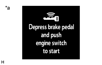
Text in Illustration *a Smart Warning Light Displayed After getting into the vehicle while carrying the key when the engine switch is off, if the brake pedal is depressed while the shift lever is in P or N, the smart warning light is displayed.
-
The engine starts if the engine switch is pressed when the smart warning light is displayed.
-
-
Changing the power source mode when the key does not operate correctly due to wave interference or key battery depletion:
-
Unlock the door using the built-in mechanical key and get into the vehicle while carrying the key.
-
While depressing the brake pedal, and facing the logo side of the key towards the engine switch, hold the key near the engine switch.
-
A buzzer in the combination meter assembly sounds and the power source mode changes to on (IG). Pressing the engine switch without depressing the brake pedal turns the power source mode from on (IG) to off.
-
-
Starting the engine when the key does not operate correctly due to wave interference or key battery depletion:
-
Unlock the door using the built-in mechanical key and get into the vehicle while carrying the key.
-
While depressing the brake pedal with the shift lever in P or N*, while facing the logo side of the key towards the engine switch, hold the key near the engine switch.
Tech Tips
*: This is only applicable when the steering wheel unlocked.
-
A buzzer in the combination meter assembly sounds, the power source mode changes to on (IG) and the smart warning light is displayed.
-
Press the engine switch with the brake pedal depressed to start the engine.
-
-
-
CHECK PUSH-BUTTON START FUNCTION
-
Check the push-button start function:
-
Get into the vehicle while carrying the key with the engine switch off. With the shift lever in P, check that the smart warning light is displayed when the brake pedal is depressed. Then check that the engine starts when the engine switch is pressed after the smart warning light is displayed.
-
While the brake pedal is released and the key is being carried, check that the power source mode changes in the following order when the engine switch is pressed: off → on (ACC) → on (IG) → off.
Tech Tips
When the engine switch is pressed with the engine switch on (IG) and the shift lever not in P, the power source mode does not change to off, but changes to on (ACC).
-
With the shift lever in P, check that the steering lock operates when a door is opened.
Tech Tips
When the engine switch is pressed after the vehicle is stopped, the engine stops and all the power turns off. However, if the shift lever is not in P when the engine switch is pressed with the vehicle stopped, the power source mode does not change to off, but changes to on (ACC).
-
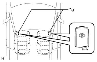
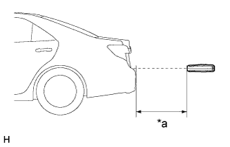
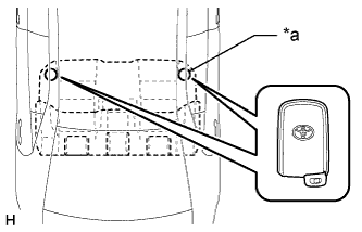
Text in Illustration *a Inspection Point Check the push-button start function operation range for the front side. Place the key in either of the two locations making sure that the key is oriented as shown in the illustration, and then check that the engine can be started.
Note
-
Even if the key is in a vehicle interior key detection area, the key may not be properly detected if the key is on the instrument panel, in the glove box or on the floor.
-
If the key is within 0.2 m (0.66 ft.) of the shift lever, communication may not be possible.
Tech Tips
Perform this inspection for both inspection points.
-
-
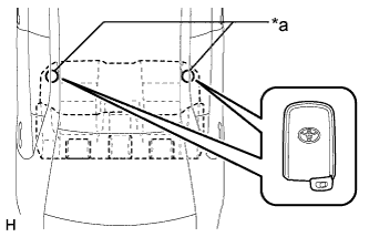
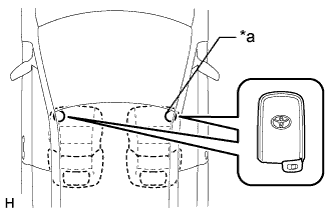
Text in Illustration *a Inspection Point Check the push-button start function operation range for the rear side. Place the key in either of the two locations making sure that the key is oriented as shown in the illustration, and then check that the engine can be started.
Note
-
Even if the key is in a vehicle interior key detection area, the key may not be properly detected if the key is on the instrument panel, in the glove box or on the floor.
-
If the key is within 0.2 m (0.66 ft.) of the center of the rear seat, communication may not be possible.
Tech Tips
Perform this inspection for both inspection points.
-
-
-
Check the key lock-in prevention function (in luggage compartment).
-
Place the electrical key transmitter sub-assembly in the luggage compartment with all doors locked. Check that) closing the luggage compartment door triggers the key wireless buzzer (which lasts approximately 2 seconds), and 2) pressing the luggage door opening switch assembly opens the luggage compartment door.
-
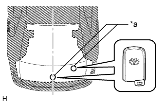
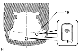
Text in Illustration *a Inspection Point Inspect the key lock-in prevention detection area. Pay attention to the direction of the electrical key transmitter sub-assembly shown in the illustration. When the electrical key transmitter sub-assembly is in either of the 2 locations in the illustration, check that: 1) closing the luggage compartment door sounds the wireless buzzer, and 2) pressing the luggage door opening switch assembly opens the luggage compartment door.
-
Text in Illustration *a 0.1 m or more (0.328 ft. or more) Inspect the key lock-in prevention detection area and the door control receiver for wave leaks. Hold the electrical key transmitter sub-assembly at the same height as the lower edge of the luggage compartment door aligning it with the center of the rear of the vehicle. Pay attention to the direction and position of the electrical key transmitter sub-assembly shown in the illustration.
Tech Tips
-
When the electrical key transmitter sub-assembly is over 0.1 m (0.328 ft.) from the rear bumper, the wireless buzzer does not sound.
-
If the warning buzzer sounds, the No. 3 indoor electrical key antenna (inside luggage compartment) may have a wave leak.
-
-
-
-
KEY DIAGNOSTIC MODE (GTS)
Tech Tips
-
With key diagnostic mode, it is possible to check if the electrical key transmitter sub-assembly is operating properly with the selected electrical key antenna and within the selected detection area by the sounding of the wireless buzzer.
-
If the buzzer sounds with [CH1] displayed but not with [CH2], the electrical key transmitter sub-assembly cannot be detected by channel 2 due to a malfunction, such as wave interference.
-
Enter the following menus: Body Electrical / Entry & Start / Utility / Communication Check (Key Diag Mode).
-
Inspect the appropriate item according to the following table.
Tester Display Inspection Item [CH1/CH2] Overhead + Driver Side No available [CH1] Overhead + Driver Side [CH2] Overhead + Driver Side [CH1/CH2] Overhead + Passenger Side No available [CH1] Overhead + Passenger Side [CH2] Overhead + Passenger Side [CH1/CH2] Overhead + Front Room*1 No. 1 indoor electrical key antenna assembly (front floor) [CH1] Overhead + Front Room*1 [CH2] Overhead + Front Room*1 [CH1/CH2] Overhead + Rear Room*2 No. 2 indoor electrical key antenna assembly (rear floor) [CH1] Overhead + Rear Room*2 [CH2] Overhead + Rear Room*2 [CH1/CH2] Overhead + Luggage No available [CH1] Overhead + Luggage [CH2] Overhead + Luggage [CH1/CH2] Luggage + Luggage (inside)*3 No. 3 indoor electrical key antenna assembly (inside luggage compartment) [CH1] Luggage + Luggage (inside)*3 [CH2] Luggage + Luggage (inside)*3 [CH1/CH2] Luggage + Luggage No available [CH1] Luggage + Luggage [CH2] Luggage + Luggage [CH1/CH2] Immobiliser Amp*4 Amplifier (engine switch) [CH1] Immobiliser Amp*4 [CH2] Immobiliser Amp*4
-
[CH1]: Channel 1 is set.
-
[CH2]: Channel 2 is set.
-
[CH1/CH2]: Channel 1 and 2 switches automatically at a specific interval*.
*: If the electrical key transmitter sub-assembly is detected with either channel 1 or 2, the buzzer sounds.
-
-
Bring the electrical key transmitter sub-assembly near the selected electrical key antenna and check that the wireless door lock buzzer sounds.
Tech Tips
The buzzer sounds in short, repeated beeps for all items except "Overhead + Rear Room"*2. For "Overhead + Rear Room"*2, the buzzer sounds in one long, continuous beep.
-
Text in Illustration *a Inspection Point *1: No. 1 indoor electrical key antenna assembly (front floor)
Tech Tips
Place the electrical key transmitter sub-assembly on the front seat cushion of the driver seat or front passenger seat.
-
Text in Illustration *a Inspection Point *2: No. 2 indoor electrical key antenna assembly (rear floor)
Tech Tips
Place the electrical key transmitter sub-assembly on the rear seat cushion.
-
Text in Illustration *a Inspection Point *3: No. 3 indoor electrical key antenna (inside luggage compartment)
Tech Tips
Place the electrical key transmitter sub-assembly in the luggage compartment. Even if the electrical key transmitter sub-assembly is in the luggage compartment, the buzzer may not sound.
-
*4: Amplifier (engine switch)
-
-
Check transmitter battery saving function
-
Check the transmitter battery saving function:
-
Press the unlock button of the electrical key transmitter sub-assembly twice while pressing the lock button and check that the electrical key transmitter sub-assembly LED blinks 4 times and enters transmitter battery saving mode.
-
Check that the push-button start does not operate while in transmitter battery saving mode.
Tech Tips
To cancel transmitter battery saving mode, press a button of the electrical key transmitter sub-assembly.
-
-
-
CHECK POWER SOURCE MODE CHANGING FUNCTION
-
Check the engine switch.
-
Check that the power source mode changes according to the chart below.
Shift Position Brake Pedal Power Source Mode when Engine Switch Pressed P Released Off → on (ACC) → on (IG) → off P Released Engine running → off P Released On (ACC)*1 → off P Depressed Off → engine starts P Depressed On (ACC) → engine starts P Depressed On (IG) → engine starts P Depressed Engine running → off P Depressed On (ACC)*1 → off N Released Off → on (ACC) → on (IG) (after power source mode changes to on (IG), power source mode changes between on (IG) and on (ACC) every time engine switch is pressed) N Released Engine running → on (ACC) N Depressed Off → engine starts*2 N Depressed On (ACC) → engine starts*2 N Depressed On (IG) → engine starts*2 N Depressed Engine running → on (ACC) Not P or N Released Off → on (ACC) → on (IG) (after power source mode changes to on (IG), power source mode changes between on (IG) and on (ACC) every time engine switch is pressed) Not P or N Released Engine running → on (ACC) Not P or N Depressed Off → on (IG) Not P or N Depressed On (ACC) → on (IG) Not P or N Depressed Engine running → on (ACC) Tech Tips
-
*1: This situation is only applicable when the power source mode has changed from on (IG) to on (ACC).
-
*2: This situation is only applicable when the steering is unlocked.
-
-
-
-
CHECK POWER SOURCE MODE INDICATION
-
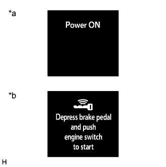
Text in Illustration *a Power ON display *b Smart Warning Light display Check the smart warning.
Multi-information Display Inspection Power Source Mode Multi-information Display Off
(Excluding condition in which the engine can be started)
Off On (ACC)
(Excluding condition in which the engine can be started)
"Power ON" displayed On (IG)
(Excluding condition in which the engine can be started)
"Power ON" displayed Condition in which engine can be started*1 Smart Warning Light displayed Engine started Off Tech Tips
*1: Indicates the condition in which the engine can be started by pressing the engine switch while either of the following conditions is met:
-
Condition 1
All of the following conditions are met:
-
The power source mode was turned from on (IG) to on (ACC).
-
Key verification is OK*2 or immobiliser is unset (engine switch is on (ACC) or on (IG)).
-
The shift lever is in N and the steering is unlocked.
-
The stop light switch is on.
-
Condition 2
All of the following conditions are met:
-
The power source mode was not turned from on (IG) to on (ACC).
-
Key verification is OK*2 or immobiliser is unset (engine switch is on (ACC) or on (IG)).
-
The stop light switch is on.
-
The shift lever is in P, or the shift lever is in N with the steering unlocked.
*2: When the key is in the vehicle, the ID code sent as a result from communication between the key and certification ECU (smart key ECU assembly) and the ID code calculated by the certification ECU (smart key ECU assembly) are compared. If the ID codes match each other, the vehicle recognizes that the key is in the vehicle.
-
-