UNLOCK WARNING SWITCH INSTALLATION

-
INSTALL UNLOCK WARNING SWITCH ASSEMBLY
-
Engage the 2 claws and install the unlock warning switch assembly to the steering column upper bracket.
-
Connect the connector.
-
-
ALIGN FRONT WHEELS FACING STRAIGHT AHEAD
-
INSPECT STEERING WHEEL CENTER POINT
-
INSTALL IGNITION SWITCH LOCK CYLINDER ASSEMBLY
-
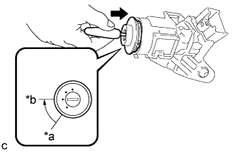
Text in Illustration *a LOCK *b ACC Make sure that the ignition switch lock cylinder assembly is in the ACC position.
-
Install the ignition switch lock cylinder assembly to the steering column upper bracket assembly.
-
Make sure that the ignition switch lock cylinder assembly is securely installed.
-
-
INSTALL TRANSPONDER KEY AMPLIFIER
-
Connect the connector to the transponder key coil.
-
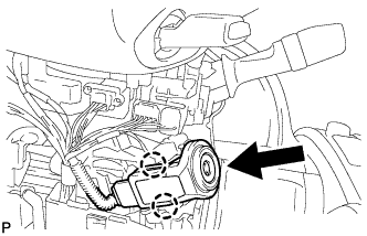
Engage the 2 claws and install the transponder key coil.
-
-
INSTALL UPPER STEERING COLUMN COVER
-
Engage the 2 claws to install the upper steering column cover.
-
Engage the 4 clips and 2 guides to install the instrument cluster finish panel to the upper steering column cover.
-
-
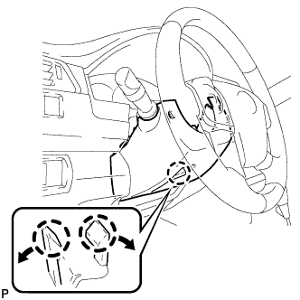
INSTALL LOWER STEERING COLUMN COVER
Note
If the lower steering column cover is installed in the incorrect order, it will not be possible to assemble the steering column cover.
-
Engage the 2 claws.
-
Engage the 2 claws.
Tech Tips
Press the area around the claws to engage them.
-
Turn the steering wheel assembly to the left and install the screw.
- Torque:
- 2.0 N*m { 20 kgf*cm, 18 in.*lbf }
-
Turn the steering wheel assembly to the right and install the lower steering column cover with the screw.
- Torque:
- 2.0 N*m { 20 kgf*cm, 18 in.*lbf }
-
-
CONNECT CABLE TO NEGATIVE BATTERY TERMINAL
Note
When disconnecting the cable, some systems need to be initialized after the cable is reconnected Click here.