CAN COMMUNICATION SYSTEM Check CAN Bus Lines for Short Circuit (LHD Models)
DESCRIPTION
There may be a short circuit between the V bus main lines and/or CAN branch lines when the resistance between terminals 6 (CANH) and 14 (CANL) of the DLC3 is below 54 Ω.
| Symptom | Trouble Area |
|---|---|
| Resistance between terminals 6 (CANH) and 14 (CANL) of DLC3 is below 54 Ω. |
|
*1: w/ AFS
*2: w/ Toyota Parking Assist-sensor System
*3: w/ Smart Entry and Start System
*4: for Navigation Receiver Type
*5: for Radio and Display Type
*6: w/ Network Gateway ECU
*7: w/ Automatic High Beam System
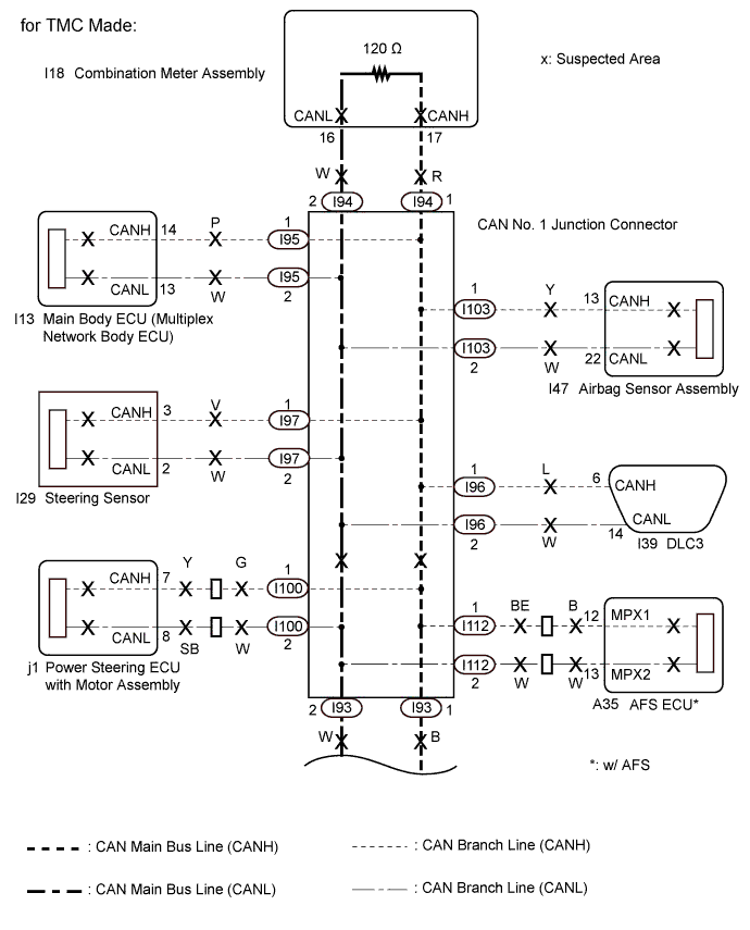
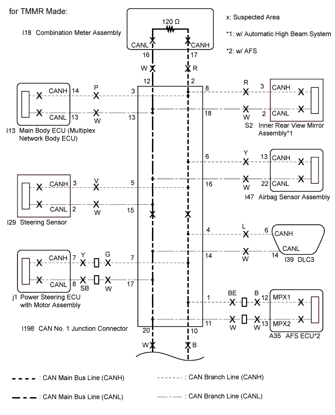
WIRING DIAGRAM
INSPECTION PROCEDURE
Note
-
Before measuring the resistance of the CAN bus, turn the ignition switch off and leave the vehicle for 1 minute or more without operating the key or any switches, or opening or closing the doors. After that, disconnect the cable from the negative (-) battery terminal and leave the vehicle for 1 minute or more before measuring the resistance.
-
After turning the ignition switch off, waiting time may be required before disconnecting the cable from the negative (-) battery terminal. Therefore, make sure to read the disconnecting the cable from the negative (-) battery terminal notices before proceeding with work Click here.
-
Because the order of diagnosis is important to allow correct diagnosis, make sure to begin troubleshooting using How to Proceed with Troubleshooting when CAN communication system related DTCs are output Click here.
-
After performing repairs, perform the DTC check procedure and confirm that the DTCs are not output again.
-
DTC check procedure: Turn the ignition switch to ON, wait at least 31 seconds, and then drive the vehicle at a speed of 20 km/h (12 mph) or more for at least 5 minutes. Check that the warning light remains off after turning off following the initial light check.
-
After the repair, perform CAN bus check and check that all the ECUs and sensors connected to the CAN communication system are displayed Click here.
Tech Tips
-
Operating the ignition switch, any other switches or a door triggers related ECU and sensor communication on the CAN. This communication will cause the resistance value to change.
-
Even after DTCs are cleared, if a DTC is stored again after driving the vehicle for a while, the malfunction may be occurring due to vibration of the vehicle. In such a case, wiggling the ECUs or wire harness while performing the inspection below may help determine the cause of the malfunction.
-
Connectors that connect to the CAN junction connector can be distinguished by the color of their CAN bus lines. When the connectors have been disconnected from the CAN junction connector, reconnecting the connectors to non-original positions on the CAN junction connector does not affect system performance. However, it is preferred to reconnect the connectors to their original positions to avoid negative effects on the wiring such as tension on the wire harnesses, and to make future maintenance easier.
PROCEDURE
-
CHECK VEHICLE TYPE
-
Check vehicle type.
Result Result Proceed to for TMC Made A for TMMR Made B
B 
CHECK FOR SHORT IN CAN BUS LINES (CAN NO. 1 JUNCTION CONNECTOR) Click here
A 
-
-
CHECK FOR SHORT IN CAN BUS LINES (DLC3 BRANCH LINE)
-
Disconnect the cable from the negative (-) battery terminal.
-
Text in Illustration *a Rear view of wire harness connector
(to CAN No. 1 Junction Connector)
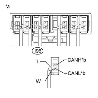
*b to DLC3 Disconnect the DLC3 branch line connector (I96) from the CAN No. 1 junction connector.
Note
-
Before disconnecting the connector, make a note of where it is connected.
-
Reconnect the connector to its original position.
-
-
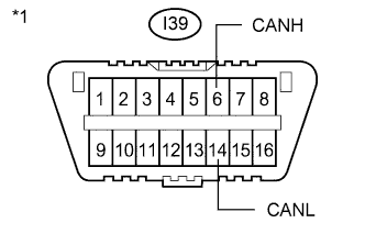
Text in Illustration *1 DLC3 Measure the resistance according to the value(s) in the table below.
Standard Resistance Tester Connection Condition Specified Condition I39-6 (CANH) - I39-14 (CANL) Cable disconnected from negative (-) battery terminal 1 MΩ or higher
NG 
REPAIR OR REPLACE CAN BRANCH LINE CONNECTED TO DLC3
OK
-
-
CHECK FOR SHORT IN CAN BUS LINES (BRANCH LINE)
-
Reconnect the DLC3 branch line connector (I96) to the CAN No. 1 junction connector.
-
Text in Illustration *1 DLC3 Connect the probes of an ohmmeter to terminals 6 (CANH) and 14 (CANL) of the DLC3.
-
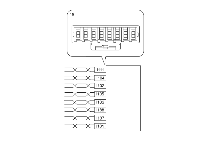
While observing the resistance value shown on the tester, disconnect connectors (I95, I97, I100, I102, I103, I105, I106, I107, I111, I112 and I188) from the CAN No. 1 junction connector or CAN No. 2 junction connector one by one until the resistance becomes normal (between 54 and 69 Ω).
Tech Tips
Disconnect the branch line connectors other than those of the DLC3.
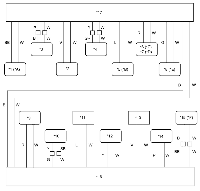
Text in Illustration *A w/ Toyota Parking Assist-sensor System *B w/ Smart Entry and Start System *C for Navigation Receiver Type *D for Radio and Display Type *E w/ Network Gateway ECU *F w/ AFS *1 Clearance Warning ECU Assembly *2 Air Conditioning Amplifier Assembly *3 ECM *4 Brake Actuator Assembly *5 Smart Key ECU Assembly (Certification ECU) *6 Navigation Receiver Assembly *7 Radio and Display Receiver Assembly *8 Network Gateway ECU *9 Combination Meter Assembly *10 Power Steering ECU with Motor Assembly *11 DLC3 *12 Airbag Sensor Assembly *13 Steering Sensor *14 Main Body ECU (Multiplex Network Body ECU) *15 AFS ECU *16 CAN No. 1 Junction Connector *17 CAN No. 2 Junction Connector - - 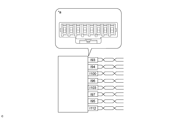
Text in Illustration *a Component without harness connected
(CAN No. 1 Junction Connector)
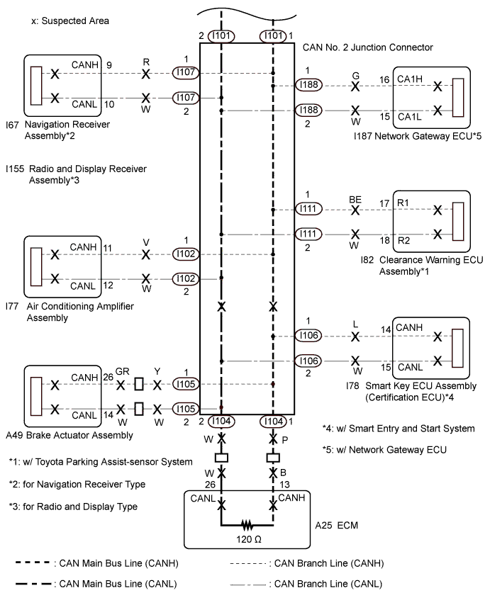
- - Wiring Color CAN No. 1 Junction Connector Side Code Color (CANH Side) Color (CANL Side) AFS ECU* I112 BE W Main body ECU (Multiplex network body ECU) I95 P W Steering sensor I97 V W Airbag sensor assembly I103 Y W DLC3 I96 L W Power steering ECU with motor assembly I100 G W Combination meter assembly I94 R W CAN main bus line (bus line connecting CAN No. 1 junction connector and CAN No. 2 junction connector) I93 B W *: w/ AFS
Text in Illustration *a Component without harness connected
(CAN No. 2 Junction Connector)
- - Wiring Color CAN No. 2 Junction Connector Side Code Color (CANH Side) Color (CANL Side) CAN main bus line (bus line connecting CAN No. 1 junction connector and CAN No. 2 junction connector) I101 B W Air conditioning amplifier assembly I102 V W ECM I104 P W Smart key ECU assembly (Certification ECU)*1 I106 L W Clearance warning ECU assembly*2 I111 BE W Network Gateway ECU*3 I188 G W
-
Navigation receiver assembly*4
-
Radio and display receiver assembly*5
I107 R W Brake actuator assembly I105 Y W *1: w/ Smart Entry and Start System
*2: w/ Toyota Parking Assist-sensor System
*3: w/ Network Gateway ECU
*4: for Navigation Receiver Type
*5: for Radio and Display Type
Note
Do not reconnect the disconnected connectors until this inspection is complete because there may be a short in 2 or more branch lines.
Result Symptom Proceed to The resistance is still below 54 Ω when all the specified connectors are disconnected. (There are no shorts between a pair of the branch lines.) A The resistance becomes normal (between 54 and 69 Ω) when a connector is disconnected. (There is a short between one or more pairs of branch lines.) B -
-
When there is a short in one or more of the branch lines:
-
Reconnect all of the connectors to the CAN junction connector, except for the one that was disconnected last (the short-circuited bus line). Check that the resistance shown on the tester is normal (between 54 and 69 Ω) to confirm that there is a short in the one branch line only.
Tech Tips
-
Connectors that connect to the CAN junction connector can be distinguished by the color of their CAN bus lines.
-
Reconnecting the connectors to non-original positions on the CAN junction connector does not affect system performance. However, it is preferred to reconnect the connectors to their original positions to avoid negative effects on the wiring such as tension on the wire harnesses, and to make future maintenance easier.
-
-
B
CHECK FOR SHORT IN CAN BUS LINES (ECU, SENSOR) Click here
A
-
-
CHECK FOR SHORT IN CAN BUS LINES (COMBINATION METER ASSEMBLY MAIN LINE)
-
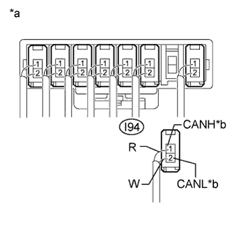
Text in Illustration *a Rear view of wire harness connector
(to CAN No. 1 Junction Connector)
*b to Combination Meter Assembly Disconnect the combination meter assembly main bus line connector (I94) from the CAN No. 1 junction connector.
Note
-
Before disconnecting the connector, make a note of where it is connected.
-
Reconnect the connector to its original position.
-
-
Text in Illustration *1 DLC3 Measure the resistance according to the value(s) in the table below.
Standard Resistance Tester Connection Condition Specified Condition I39-6 (CANH) - I39-14 (CANL) Cable disconnected from negative (-) battery terminal 108 to 132 Ω Result Symptom Proceed to The resistance is still below 54 Ω when the combination meter assembly connector is disconnected. (There are no shorts in the combination meter assembly or between its main bus lines.) A The resistance falls within the specified range (between 108 and 132 Ω) (the other terminating resistor is normal) when the combination meter assembly connector is disconnected. (There is a short in the combination meter assembly or between its main bus lines.) B
B
CHECK FOR SHORT IN CAN BUS LINES (COMBINATION METER ASSEMBLY) Click here
A
-
-
CHECK FOR SHORT IN CAN BUS LINE (ECM MAIN LINE)
-
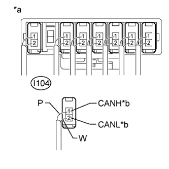
Text in Illustration *a Rear view of wire harness connector
(to CAN No. 2 Junction Connector)
*b to ECM Disconnect the ECM main bus line connector (I104) from the CAN No. 2 junction connector.
Note
-
Before disconnecting the connector, make a note of where it is connected.
-
Reconnect the connector to its original position.
-
-
Text in Illustration *1 DLC3 Measure the resistance according to the value(s) in the table below.
Standard Resistance Tester Connection Condition Specified Condition I39-6 (CANH) - I39-14 (CANL) Cable disconnected from negative (-) battery terminal 1 MΩ or higher Tech Tips
Measure the resistance with the combination meter assembly main bus line connector (I94) disconnected.
Result Symptom Proceed to The resistance is still below 1 MΩ when the ECM connector is disconnected. (There are no shorts in the ECM or between its main bus lines.) A The resistance becomes 1 MΩ or higher when the ECM connector is disconnected. (There is a short in the ECM or between its main bus lines.) B
B
CHECK FOR SHORT IN CAN BUS LINES (ECM) Click here
A
-
-
CHECK CAN NO. 1 JUNCTION CONNECTOR
-
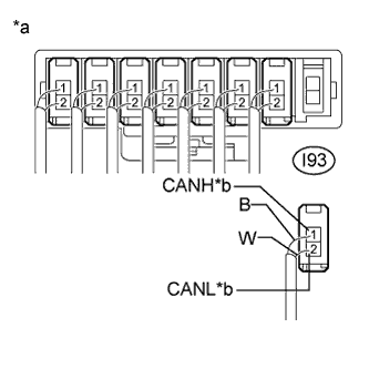
Text in Illustration *a Rear view of wire harness connector
(to CAN No. 1 Junction Connector)
*b to CAN No. 2 Junction Connector Disconnect the CAN main bus line connector (I93) from the CAN No. 1 junction connector.
Note
-
Before disconnecting the connector, make a note of where it is connected.
-
Reconnect the connector to its original position.
-
-
Text in Illustration *1 DLC3 Measure the resistance according to the value(s) in the table below.
Standard Resistance Tester Connection Condition Specified Condition I39-6 (CANH) - I39-14 (CANL) Cable disconnected from negative (-) battery terminal 1 MΩ or higher
NG
REPLACE CAN NO. 1 JUNCTION CONNECTOR
OK
-
-
CHECK CAN NO. 2 JUNCTION CONNECTOR (CAN NO. 1 J/C - CAN NO. 2 J/C)
-
Reconnect the CAN main bus line connector (I93) to the CAN No. 1 junction connector.
-
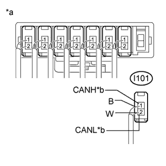
Text in Illustration *a Rear view of wire harness connector
(to CAN No. 2 Junction Connector)
*b to CAN No. 1 Junction Connector Disconnect the CAN main bus line connector (I101) from the CAN No. 2 junction connector.
Note
-
Before disconnecting the connector, make a note of where it is connected.
-
Reconnect the connector to its original position.
-
-
Text in Illustration *1 DLC3 Measure the resistance according to the value(s) in the table below.
Standard Resistance Tester Connection Condition Specified Condition I39-6 (CANH) - I39-14 (CANL) Cable disconnected from negative (-) battery terminal 1 MΩ or higher
NG
REPAIR OR REPLACE CAN BUS MAIN LINES (CAN NO. 1 JUNCTION CONNECTOR - CAN NO. 2 JUNCTION CONNECTOR)
OK 
REPLACE CAN NO. 2 JUNCTION CONNECTOR
-
-
CHECK FOR SHORT IN CAN BUS LINES (ECU, SENSOR)
-
Reconnect the connector for the short-circuited branch line to the CAN junction connector (the connector that caused the bus line resistance to become normal (between 54 and 69 Ω) when it was disconnected).
-
Disconnect the connector that includes the DLC3 connected CAN lines (such as CANH and CANL) from the ECU or sensor to which the short-circuited branch line is connected Click here.
-
Text in Illustration *1 DLC3 Measure the resistance according to the value(s) in the table below.
Standard Resistance Tester Connection Condition Specified Condition I39-6 (CANH) - I39-14 (CANL) Cable disconnected from negative (-) battery terminal 54 to 69 Ω Tech Tips
If the resistance becomes normal (between 54 and 69 Ω) when the connector is disconnected from the ECU or sensor, there may be a short in the ECU or sensor.
NG
REPAIR OR REPLACE CORRESPONDING ECU OR SENSOR BRANCH LINES OR CONNECTOR
OK
REPLACE CORRESPONDING ECU OR SENSOR
-
-
CHECK FOR SHORT IN CAN BUS LINES (COMBINATION METER ASSEMBLY)
-
Reconnect the combination meter assembly main bus line connector (I94) to the CAN No. 1 junction connector.
-
Disconnect the I18 combination meter assembly connector.
-
Text in Illustration *1 DLC3 Measure the resistance according to the value(s) in the table below.
Standard Resistance Tester Connection Condition Specified Condition I39-6 (CANH) - I39-14 (CANL) Cable disconnected from negative (-) battery terminal 108 to 132 Ω Tech Tips
If the resistance becomes normal (between 108 to 132 Ω) when the connector is disconnected, there may be a short in the combination meter assembly.
NG
REPAIR OR REPLACE CAN BUS MAIN LINES (COMBINATION METER ASSEMBLY MAIN LINES)
OK
REPLACE COMBINATION METER ASSEMBLY Click here
-
-
CHECK FOR SHORT IN CAN BUS LINES (ECM)
-
Reconnect the ECM main bus line connector (I104) to the CAN No. 2 junction connector.
-
Disconnect the A25 ECM connector.
-
Text in Illustration *1 DLC3 Measure the resistance according to the value(s) in the table below.
Standard Resistance Tester Connection Condition Specified Condition I39-6 (CANH) - I39-14 (CANL) Cable disconnected from negative (-) battery terminal 1 MΩ or higher Result Result Proceed to OK (for 2GR-FE) A OK (for 2AR-FE) B NG C Tech Tips
-
Measure the resistance with the combination meter assembly main bus line connector (I94) disconnected.
-
If the resistance changes to 1 MΩ or higher when the connector is disconnected, there may be a short in the ECM.
-
B
REPLACE ECM Click here
C
REPAIR OR REPLACE CAN BUS MAIN LINES (ECM MAIN LINES)
A
REPLACE ECM Click here
-
-
CHECK FOR SHORT IN CAN BUS LINES (CAN NO. 1 JUNCTION CONNECTOR)
-
Disconnect the I198 CAN No. 1 junction connector.
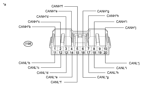
Text in Illustration *a Front view of wire harness connector
(to CAN No. 1 Junction Connector)
*b to AFS ECU*1
(for V Bus)
*c to Combination Meter Assembly
(for V Bus)
*d to Main Body ECU (Multiplex Network Body ECU)
(for V Bus)
*e to DLC3
(for V Bus)
*f to Steering Sensor
(for V Bus)
*g to Airbag Sensor Assembly
(for V Bus)
*h to Power Steering ECU with Motor Assembly
(for V Bus)
*i to Inner Rear View Mirror Assembly*2
(for V Bus)
*j to CAN No. 2 Junction Connector
(for V Bus)
*1: w/ AFS
*2: w/ Automatic High Beam System
-
Measure the resistance according to the value(s) in the table below.
Standard Resistance Tester Connection Condition Specified Condition Connected to I198-1 (CANH) - I198-11 (CANL) Cable disconnected from negative (-) battery terminal 200 Ω or higher AFS ECU*1 I198-2 (CANH) - I198-12 (CANL) Cable disconnected from negative (-) battery terminal 108 to 132 Ω Combination meter assembly I198-3 (CANH) - I198-13 (CANL) Cable disconnected from negative (-) battery terminal 200 Ω or higher Main body ECU (Multiplex network body ECU) I198-4 (CANH) - I198-14 (CANL) Cable disconnected from negative (-) battery terminal 1 MΩ or higher DLC3 I198-5 (CANH) - I198-15 (CANL) Cable disconnected from negative (-) battery terminal 200 Ω or higher Steering sensor I198-6 (CANH) - I198-16 (CANL) Cable disconnected from negative (-) battery terminal 200 Ω or higher Airbag sensor assembly I198-7 (CANH) - I198-17 (CANL) Cable disconnected from negative (-) battery terminal 200 Ω or higher Power steering ECU with motor assembly I198-8 (CANH) - I198-18 (CANL) Cable disconnected from negative (-) battery terminal 200 Ω or higher Inner rear view mirror assembly*2 I198-10 (CANH) - I198-20 (CANL) Cable disconnected from negative (-) battery terminal 108 to 132 Ω CAN No. 2 junction connector *1: w/ AFS
*2: w/ Automatic High Beam System
Result Result Proceed to OK A NG (CAN No. 2 junction connector main lines) B NG (Combination meter assembly main lines) C NG (DLC3 branch line) D NG (ECU or sensor branch line) E
B
CHECK CAN NO. 2 JUNCTION CONNECTOR (CAN NO. 1 J/C - CAN NO. 2 J/C) Click here
C
CHECK FOR SHORT IN CAN BUS LINES (COMBINATION METER ASSEMBLY MAIN LINE) Click here
D
REPAIR OR REPLACE CAN BRANCH LINE CONNECTED TO DLC3
E
CHECK FOR SHORT IN CAN BUS LINES (ECU, SENSOR) Click here
A
REPLACE CAN NO. 1 JUNCTION CONNECTOR
-
-
CHECK CAN NO. 2 JUNCTION CONNECTOR (CAN NO. 1 J/C - CAN NO. 2 J/C)
-
Reconnect the I198 CAN No. 1 junction connector.
-
Text in Illustration *a Rear view of wire harness connector
(to CAN No. 2 Junction Connector)
*b to CAN No. 1 Junction Connector Disconnect the CAN main bus line connector (I101) from the CAN No. 2 junction connector.
Note
-
Before disconnecting the connector, make a note of where it is connected.
-
Reconnect the connector to its original position.
-
-
Text in Illustration *1 DLC3 Measure the resistance according to the value(s) in the table below.
Standard Resistance Tester Connection Condition Specified Condition I39-6 (CANH) - I39-14 (CANL) Cable disconnected from negative (-) battery terminal 108 to 132 Ω
NG
REPAIR OR REPLACE CAN BUS MAIN LINES (CAN NO. 1 JUNCTION CONNECTOR - CAN NO. 2 JUNCTION CONNECTOR)
OK
-
-
CHECK FOR SHORT IN CAN BUS LINES (CAN NO. 2 JUNCTION CONNECTOR)
-
Reconnect the CAN main bus line connector (I101) to CAN No. 2 junction connector.
-
Text in Illustration *1 DLC3 Connect the probes of an ohmmeter to terminals 6 (CANH) and 14 (CANL) of the DLC3.
-
While observing the resistance value shown on the tester, disconnect connectors (I102, I105, I106, I107, I111 and I188) from the CAN No. 2 junction connector one by one until the resistance becomes normal (between 54 and 69 Ω).

Text in Illustration *a Component without harness connected
(CAN No. 2 Junction Connector)
- - Wiring Color CAN No. 2 Junction Connector Side Code Color (CANH Side) Color (CANL Side) CAN main bus line (bus line connecting CAN No. 1 junction connector and CAN No. 2 junction connector) I101 B W Air conditioning amplifier assembly I102 V W ECM I104 P W Smart key ECU assembly (Certification ECU)*1 I106 L W Clearance warning ECU assembly*2 I111 BE W
-
Navigation receiver assembly*3
-
Radio and display receiver assembly*4
I107 R W Network Gateway ECU*5 I188 G W Brake actuator assembly I105 Y W *1: w/ Smart Entry and Start System
*2: w/ Toyota Parking Assist-sensor System
*3: for Navigation Receiver Type
*4: for Radio and Display Type
*5: w/ Network Gateway ECU
Note
Do not reconnect the disconnected connectors until this inspection is complete because there may be a short in 2 or more branch lines.
Result Symptom Proceed to The resistance is still below 54 Ω when all the specified connectors are disconnected. (There are no shorts between a pair of the branch lines.) A The resistance becomes normal (between 54 and 69 Ω) when a connector is disconnected. (There is a short between one or more pairs of branch lines.) B -
-
When there is a short in one or more of the branch lines:
-
Reconnect all of the connectors to the CAN junction connector, except for the one that was disconnected last (the short-circuited bus line). Check that the resistance shown on the tester is normal (between 54 and 69 Ω) to confirm that there is a short in the one branch line only.
Tech Tips
-
Connectors that connect to the CAN junction connector can be distinguished by the color of their CAN bus lines.
-
Reconnecting the connectors to non-original positions on the CAN junction connector does not affect system performance. However, it is preferred to reconnect the connectors to their original positions to avoid negative effects on the wiring such as tension on the wire harnesses, and to make future maintenance easier.
-
-
B
CHECK FOR SHORT IN CAN BUS LINES (ECU, SENSOR) Click here
A
-
-
CHECK FOR SHORT IN CAN BUS LINES (ECM MAIN LINE)
-
Text in Illustration *a Rear view of wire harness connector
(to CAN No. 2 Junction Connector)
*b to ECM Disconnect the ECM main bus line connector (I104) from the CAN No. 2 junction connector.
Note
-
Before disconnecting the connector, make a note of where it is connected.
-
Reconnect the connector to its original position.
-
-
Text in Illustration *1 DLC3 Measure the resistance according to the value(s) in the table below.
Standard Resistance Tester Connection Condition Specified Condition I39-6 (CANH) - I39-14 (CANL) Cable disconnected from negative (-) battery terminal 108 to 132 Ω Result Symptom Proceed to The resistance is still below 54 Ω when the ECM connector is disconnected. (There are no shorts in the ECM or between its main bus lines.) A The resistance becomes normal (between 108 to 132 Ω) when the ECM connector is disconnected. (There is a short in the ECM or between its main bus lines.) B
B
CHECK FOR SHORT IN CAN BUS LINES (ECM) Click here
A
REPLACE CAN NO. 2 JUNCTION CONNECTOR
-
-
CHECK FOR SHORT IN CAN BUS LINES (COMBINATION METER ASSEMBLY MAIN LINE)
-
Reconnect the I198 CAN No. 1 junction connector.
-
Disconnect the I18 combination meter assembly connector.
-
Text in Illustration *1 DLC3 Measure the resistance according to the value(s) in the table below.
Standard Resistance Tester Connection Condition Specified Condition I39-6 (CANH) - I39-14 (CANL) Cable disconnected from negative (-) battery terminal 108 to 132 Ω Tech Tips
If the resistance becomes normal (between 108 to 132 Ω) when the connector is disconnected, there may be a short in the combination meter assembly.
NG
REPAIR OR REPLACE CAN BUS MAIN LINES (COMBINATION METER ASSEMBLY MAIN LINES)
OK
REPLACE COMBINATION METER ASSEMBLY Click here
-
-
CHECK FOR SHORT IN CAN BUS LINES (ECU, SENSOR)
-
Reconnect the connector for the short-circuited branch line to the CAN junction connector (the connector that caused the bus line resistance to become normal (between 54 and 69 Ω) when it was disconnected).
-
Disconnect the connector that includes the DLC3 connected CAN lines (such as CANH and CANL) from the ECU or sensor to which the short-circuited branch line is connected Click here.
-
Text in Illustration *1 DLC3 Measure the resistance according to the value(s) in the table below.
Standard Resistance Tester Connection Condition Specified Condition I39-6 (CANH) - I39-14 (CANL) Cable disconnected from negative (-) battery terminal 54 to 69 Ω Tech Tips
If the resistance becomes normal (between 54 and 69 Ω) when the connector is disconnected from the ECU or sensor, there may be a short in the ECU or sensor.
NG
REPAIR OR REPLACE CORRESPONDING ECU OR SENSOR BRANCH LINES OR CONNECTOR
OK
REPLACE CORRESPONDING ECU OR SENSOR
-
-
CHECK FOR SHORT IN CAN BUS LINES (ECM)
-
Reconnect the ECM main bus line connector (I104) to the CAN No. 2 junction connector.
-
Disconnect the A25 ECM connector.
-
Text in Illustration *1 DLC3 Measure the resistance according to the value(s) in the table below.
Standard Resistance Tester Connection Condition Specified Condition I39-6 (CANH) - I39-14 (CANL) Cable disconnected from negative (-) battery terminal 108 to 132 Ω Result Result Proceed to OK (for 2GR-FE) A OK (for 2AR-FE) B NG C Tech Tips
If the resistance becomes normal (between 108 to 132 Ω) when the connector is disconnected, there may be a short in the ECM.
B
REPLACE ECM Click here
C
REPAIR OR REPLACE CAN BUS MAIN LINES (ECM MAIN LINES)
A
REPLACE ECM Click here
-