CAN COMMUNICATION SYSTEM SYSTEM DIAGRAM

-
OVERALL CAN BUS DIAGRAM (for LHD)
-
Control system CAN is composed of 2 buses.
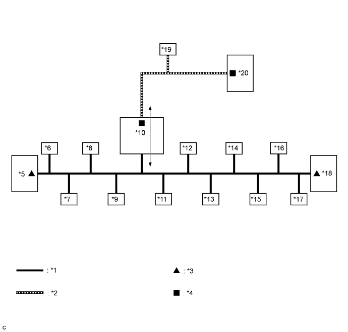
Text in Illustration *1 V Bus *2 Sub Bus 1 *3 V Bus Terminating Resistor *4 Sub Bus 1 Terminating Resistor *5 Combination Meter Assembly
(for V Bus)
*6 AFS ECU*4
(for V Bus)
*7 Airbag Sensor Assembly
(for V Bus)
*8 DLC3
(for V Bus)
*9 Power Steering ECU with Motor Assembly
(for V Bus)
*10 Main Body ECU (Multiplex Network Body ECU)
(for V Bus and Sub Bus 1)
*11 Steering Sensor
(for V Bus)
*12 Air Conditioning Amplifier Assembly
(for V Bus)
*13 Clearance Warning ECU Assembly*5
(for V Bus)
*14 Brake Actuator Assembly
(for V Bus)
*15 Smart Key ECU Assembly (Certification ECU)*3
(for V Bus)
*16
-
Navigation ECU Sub-assembly*1
-
Radio and Display Receiver Assembly*2
(for V Bus)
*17 Yaw Rate Sensor*7
(for V Bus)
*18 ECM
(for V Bus)
*19 Multiplex Tilt and Telescopic ECU*6
(for Sub Bus 1)
*20 CAN No. 5 J/C*6
(for Sub Bus 1)
*1: for Navigation receiver type
*2: for Radio and display type
*3: w/ Smart entry and start system
*4: w/ AFS
*5: w/ Toyota parking assist-sensor system
*6: w/ Power tilt and power telescopic steering column system
*7: Separate type yaw rate sensor
-
Tech Tips
-
The main body ECU (multiplex network body ECU) functions as a gateway between the V bus and sub bus 1.
-
Refer to the following bus wiring diagrams for details.
-
-
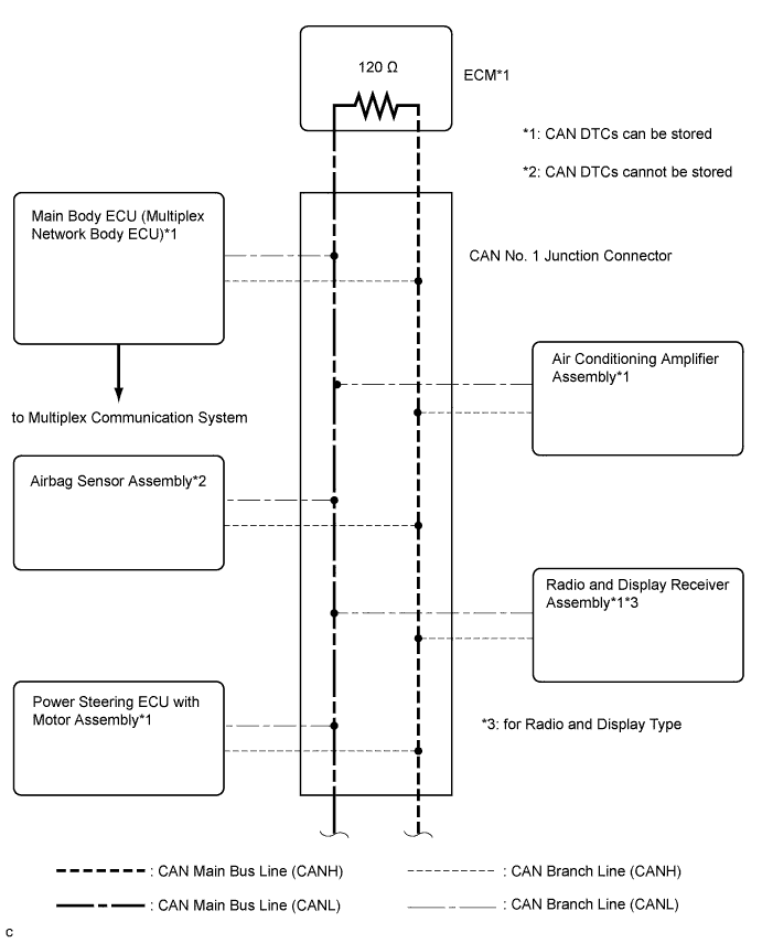
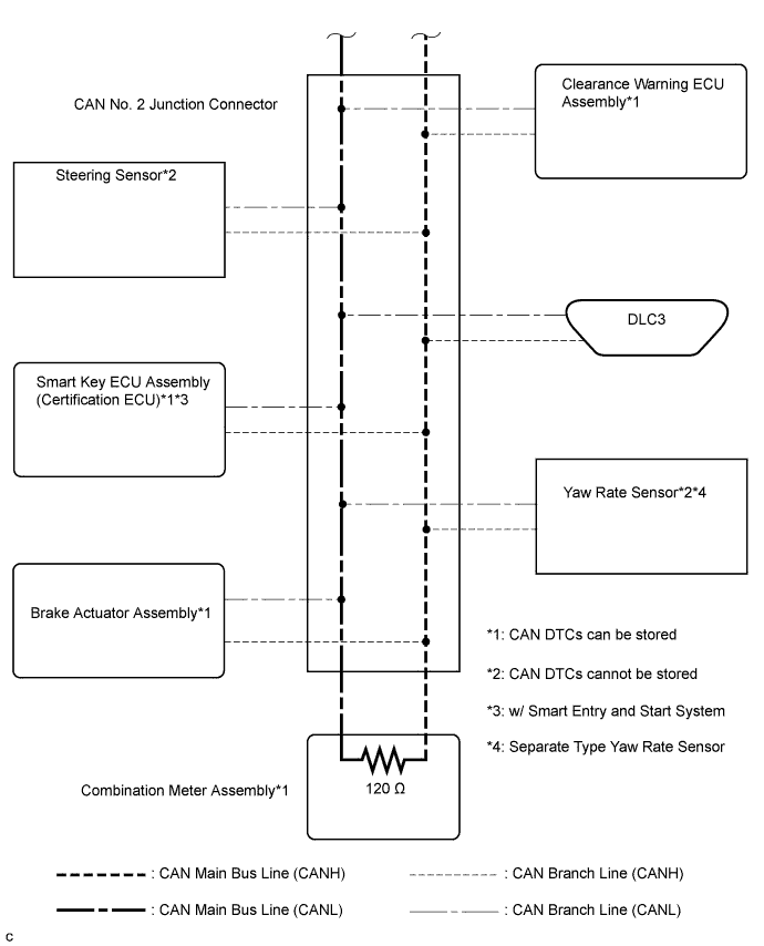
V BUS (for LHD)
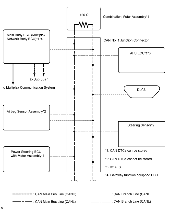
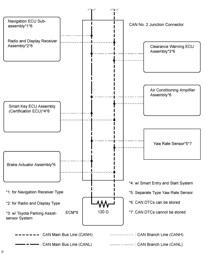
Tech Tips
The CAN communication system connects to other networks via ECUs that function as a gateway Click here.
-
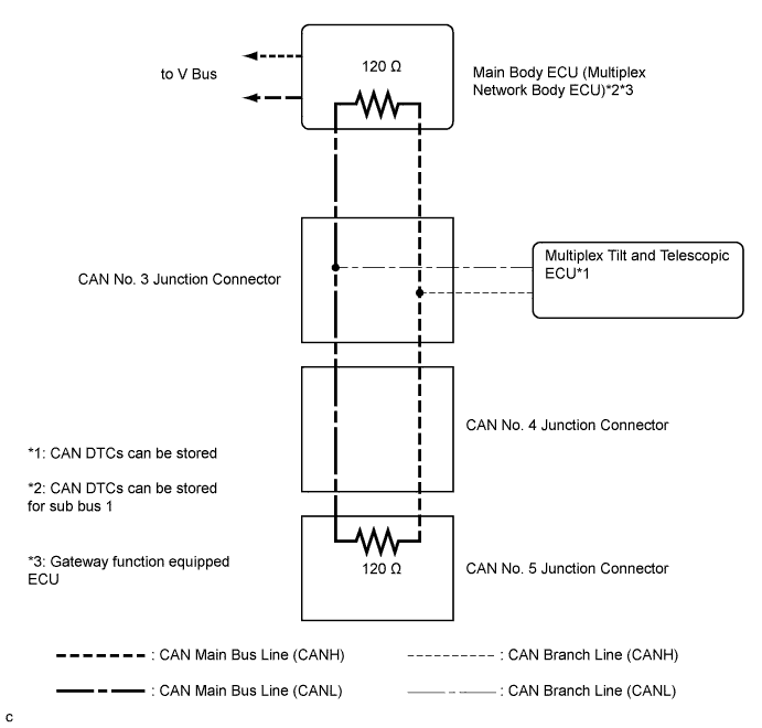
SUB BUS 1 (w/ Power Tilt and Power Telescopic Steering Column System for LHD)
-
OVERALL CAN BUS DIAGRAM (for RHD)
-
Control system CAN is composed of 1 bus.
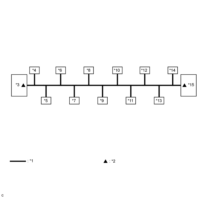
Text in Illustration *1 V Bus *2 V Bus Terminating Resistor *3 ECM
(for V Bus)
*4 Main Body ECU (Multiplex Network Body ECU)
(for V Bus)
*5 Airbag Sensor Assembly
(for V Bus)
*6 Power Steering ECU with Motor Assembly
(for V Bus)
*7 Air Conditioning Amplifier Assembly
(for V Bus)
*8 Radio and Display Receiver Assembly
(for V Bus)
*9 Steering Sensor
(for V Bus)
*10 Smart Key ECU Assembly (Certification ECU)*1
(for V Bus)
*11 Brake Actuator Assembly
(for V Bus)
*12 Clearance Warning ECU Assembly
(for V Bus)
*13 DLC3
(for V Bus)
*14 Yaw Rate Sensor*2
(for V Bus)
*15 Combination Meter Assembly
(for V Bus)
- - *1: w/ Smart entry and start system
*2: Separate type yaw rate sensor
Tech Tips
Refer to the following bus wiring diagrams for details.
-
-
V BUS (for RHD)
Tech Tips
The CAN communication system connects to other network via ECUs that function as a gateway Click here.